crwdns2915892:0crwdne2915892:0
This disassembly guide is complete enough to replace the shutter mechanism if necessary.
I initiated the disassembly because I thought the shutter assembly was broken, but upon reaching the shutter assembly, found a loose screw on the sensor mount that was causing the problem by jamming in the shutter. I fixed the sensor mount, reassembled the camera, and it works. Saved myself $2000. No way I would have disassembled a camera this expensive if it worked.
I would vote for a pretty high repairability score for this camera. Very little adhesive. The screws are all simple phillips head. I used a lot of random iFixIt tools for the connectors etc.
I marked the disassembly difficult because of the cable manipulation required removing the motherboard especially.
crwdns2942213:0crwdne2942213:0
-
-
Remove the SD cards and battery.
-
The EVF cover comes off by snapping up, no screws.
-
-
-
Remove the two bottom metal covers by removing the 8 screws. They are both held on by the same screws.
-
-
-
Remove the electronic view finder screws including the screw that holds the focus knob on.
-
To remove the focus knob screw, use a spudger to hold the focus knob from spinning while you unscrew.
-
-
-
The rubber hand grip has to be removed to reach screws underneath. Get under one corner, then peel it off slowly.
-
-
-
The screw with the red circle is shorter. Note this for reassembly.
-
-
-
More screws required to get the camera back off in one piece.
-
Notice the silver screws behind the rubber grip.
-
-
-
Remember the single screw behind the display. Required to remove the camera back.
-
-
-
The back cover requires some prying but not a lot. If it's too difficult, check for screws to remove.
-
There is just one ribbon cable connecting the entire back to remove when the back is loose. The connector is a ZIF type that flips up toward the top of the camera to loosen.
-
-
-
Notice at this point the ports covers (HDMI/headphone and USB-C/multi) kind of fall off with the back cover so when you put the back cover back on, you will have to replace these ports covers before securing the back cover.
-
-
-
There are 2 connectors to the EVF.
-
One is ZIF that loosens by flipping down.
-
The other is standard friction-fitted.
-
The EVF can be pried out gently.
-
Also carefully remove the pillow pad behind the EVF. Be careful because it can be brittle.
-
-
-
-
The 2 connectors are both ZIF and loosen by flipping up toward the top of the camera.
-
-
-
There are 7 total screws holding on the top.
-
1 screw is under where the camera is labelled a7iii. It is the silver one on the right as opposed to the black one on the left in a similar position.
-
2 screws are behind where the EVF was, partially hidden by the pad when in place. They are silver even though they look black in the photos.
-
1 screw is in the top-right facing back under where the exposure adjustment knob is. Silver.
-
1 screw is in the battery compartment. Black.
-
2 screws are under where the rubber hand-hold was.
-
-
-
Once the connectors are disconnected and the screws are out, the top comes off pretty easily.
-
-
-
Prepare a small baggie for the headphone jack parts.
-
Remove the electrical tape protecting the headphone jack. Be careful not to grab the ribbons behind the tape when you remove the tape.
-
Disconnect the connector. There is just one connector.
-
Remove the 2 screws holding the headphone jack on.
-
-
-
The anti-static tape has to be removed to access various parts. gently pry it up. Don't cut anything you can't remove yet just get it out of the way.
-
-
-
Battery connector identified by having only two conductors, each very thick. ZIF, loosens by flipping down toward bottom of the camera.
-
-
-
Connector under the processor anti-static tape is friction fit. Steady-shot cable.
-
-
-
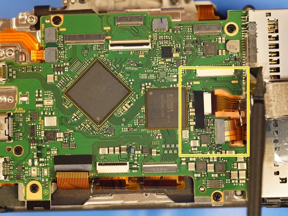
2 connectors here are ZIF, loosen by flipping down toward bottom of the camera. Both are imager connectors.
-
-
-
2 connectors under battery connector are friction-fitted. Uper one is the shutter connector. The lower one is the E-mount connector
-
-
-
External mic connector at top left is friction-fitted.
-
-
-
1 connector (under multi-port) on opposite side before flipping the motherboard up is friction-fitted.
-
On reassembly, I put the motherboard in place with one screw lightly tightened on the side of the board opposite multip-port connector, then used one of the longer screws to hold the motherboard in place but loose for more space while I inserted the multi-port connector.
-
It worked well. This connector is designed to be inserted with the motherboard in place. There is a cut-out in the motherboard that allows you to push the cable in). MB charge motor connector.
-
-
-
The 5 screws holding on the motherboard are easy to see.
-
-
-
Feed the battery connector through the hole to be able to flip the mother board up toward the top of the camera.
-
2 connectors on front side of motherboard are friction-fitted.
-
When reassembling, I initially tried to put these cables on with the motherboard in position to avoid having to feed the battery cable through with these 2 cables connected, but it turned out much easier to connect these cables first with the motherboard flipped up then flip the motherboard into place feeding the battery cable through.
-
1-wire Wi-Fi antenna connector is friction-fitted. (on reassembly, I connected the WiFi cable first, then the other two front-side cables before flipping the motherboard down into place).
-
-
-
There are 2 sticky cables that hold this block on besides the screws. Carefully remove the cables.
-
-
-
There are 4 screws that hold this block on. The screws are easy to find.
-
Remove the cover to reveal the steady-shot anti-shake sensor block.
-
-
-
The photo is with the anti-shake unit taken off.
-
BEFORE YOU TAKE THE ANTI-SHAKE OFF, be prepared to mark the numbers and locations of the shim washers. There are three positions for washers and each spot can have up to 2 washers. Mine had a total of 4 washers. The markings are the thickness in 1/100th mm and on reassembly, they should go back in the same place.
-
These washers set the flatness of the sensor to the front of the camera / lens.
-
-
-
The anti-shake unit is held on by 3 screws and flex tape.
-
Of course besides looking for the positions of the shim washers, be careful removing this piece because the sensor is attached to it and will be exposed. Furthermore, the sensor mount is flexible and fragile.
-
You can see the repaired mounts on my sensor block. The bottom screw had come out and the top mounts broke as a result. The loose bottom screw was also jamming in my shutter unit and made me think the shutter unit was broken.
-
-
-
4 screws secure the shutter unit in place. The cables are already disconnected.
-


To reassemble your device, follow these instructions in reverse order.
To reassemble your device, follow these instructions in reverse order.
crwdns2935221:0crwdne2935221:0
crwdns2935229:07crwdne2935229:0

crwdns2947412:017crwdne2947412:0
Thanks for this, I just need to replace my USB port cover that is broken and I wondered how they are held in.
Nice to know they drop off when the back is removed.
I'm glad it helped! Thanks for letting me know.
Thanks for putting the guide together! I went through this up to Step 10 to diagnose and order a replacement for a slit EVF proximity sensor cable. The cable is pinched against the top of the case, so I think my unit was just out of tolerance enough that over time repeated minor impacts cumulatively led to cutting through the cable. Other people report the same problem on reddit.
Great to hear you used the guide! Thanks for sharing.
Thank you so much for this!
It was quite clear to me, even though I had never taken a camera apart before.
A few small things that might help others:
- The missing screw in step 25 is underneath the little black tape at the top-right (right under the WiFi antenna)
- you don’t have to take the grip all the way off, you don’t need the 4 screws at the middle, so you only need to pull away the edges at the sd card side and at the top next to the dial.
Also, when I took it apart a second time (I wanted to remove the shims for the sensor), my camera didn’t want to boot anymore and just rebooted again and again by itself. This appears to be a software bug and you might have to disassemble again until step 23. There is a small battery on the other side of the copper plate which remembers the date and time settings, but that needs to be disconnected from the motherboard to fix the issue.
Hope this helps,
And thanks again!
- I was able to see where that screw is and I circled the fourth screw in the picture in step 25. Thank you for the input.
- Why did you want to remove the shims? They seem really important and if you remove them I would think the sensor could be too close to the camera housing and possibly interfere, right? I would think removing the shims could break the camera (maybe, maybe not, but I wouldn't remove them).
Thank you so much for posting this content,
I have a question about shims ?
If i want to astro modify the sensor and remove IR/UV filter from the sensor , do i need ignore those shims in reassembly for having infinity focus ? And is it possible to remove shims for solving infinty focus problem cause to remove some glass in front of the sensor?
Sounds interesting and risky to remove a filter from the sensor. I don't know much about that specifically. I can say as it says in step 26 that the shim markings are 1/100mm, so the total thickness of any of them is around half mm. I would NOT think you would want to remove the shims because they aren't just for space, they are to make the sensor flat with the camera case / lens mount. If you remove them or put them back in a different location, you undo the factory calibration of having the sensor FLAT with the image the lens is projecting. I wouldn't think you would want that at all. Also, without the shims you might have the issue of the sensor interfering with the camera case.
I would think you would just remove the filter. Although I don't really know how you would do that either because it might be glued on. I didn't see an extra filter piece you could remove easily.
hi,
my lcd display all the sudden started to show colorful strips. I assume it´s something with the ribbon cable either being corrupted or discounted. Sometimes it works sometimes it doesn't. how can i check that?
I would say maybe take it apart until you remove the ribbon cable that goes to the LCD and re-install it. If the strips aren't too bad though it might not be worth the risk.
My camera won't turn off when I switch it to OFF. Some time ago It worked 50/50 and sometimes camera turned off immediately after going to low power mode.
Not it never turns off. I tried disconnecting the power switch connector from the main board, but the camera it still turned ON. Does it mean some kind of serious issue with main board or maybe power switch is just inverted?
Sounds to me like the switch gradually went bad, but I don't know. Sounds like the camera is still usable right? Maybe take the battery out when you are done. You could try physically toggling the switch somehow but I'm not even sure it's really a "power on power off" switch or something that tells the motherboard to turn on or off.
Thank you so much for this guide! I thought I had to replace the shutter, but when opening the camera I found that only the frame around the sensor visible in picture 3 of step 27 (lighter grey just around the sensor) was loose because the screw at the bottom had completely fallen out. As I already had the new shutter I put it in anyway, as it might have been damaged by the loose frame.
If anyone knows how that frame is called or where it could be ordered as a replacement part, I would be very glad to know! For now, I just removed it and everything seems to work perfectly.
Hi Lio, glad you liked it and were able to follow! This is really fun for me to see people use the guide.
I don't know how to order that gray frame specifically. I would imagine the best way to obtain one would be to buy a broken a7iii and assume that part isn't broken since it isn't a moving part.
Notice the third bullet point in step 27. The loose screw was EXACTLY the problem I had with my camera:
"You can see the repaired mounts on my sensor block. The bottom screw had come out and the top mounts broke as a result. The loose bottom screw was also jamming in my shutter unit and made me think the shutter unit was broken."
I didn't even replace the shutter because I hadn't bought one yet so I gambled that mine was okay and put it back together and it's is still working.
Happy to hear you fixed yours!
Your guide really was the reason I would even attempt to open it!
Weird that it was the exact same screw, and good idea to look for a broken A7 III. I think I will just use mine for now (and hope the sensor does not fall apart), and if I see any problems I might try that.
Lio -
Thanks so much for this guide. I have a broken card slot (slot 2, the upper one). Is it complicated to replace it? Must I disassemble the motherboard entirely?
Thanx from Norway
Bjørn Kamfjord
I imagine you could get a replacement card slot, but I think the hardest part about that would be to de-solder the old one off and solder the new one on. I don't know how many points it's soldered on by. You get access to the card slot pretty early in this guide and then you could look and know. I wasn't paying much attention to the card slots honestly.