crwdns2915892:0crwdne2915892:0
This guide will show you how to disconnect and remove the main circuit board of the Alpha 65 camera. This requires using a Phillips #00 screwdriver, plastic opening tool, and tweezers. Be sure to keep track of all screws and parts removed from the camera.
crwdns2942213:0crwdne2942213:0
-
-
Remove the two 4.0 mm Phillips #00 screws on the base of the camera.
-
Remove the 3.0 mm Phillips #00 screw on the hinge of the screen.
-
-
-
Remove the two 2.0 mm Phillips #00 screws on the bottom-right side of the screen.
-
Remove the two 2.0 mm Phillips #00 screws on the bottom-left side of the screen.
-
-
-
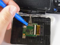
Use the plastic opening tool to gently pry the screen open around the entire screen.
-
-
-
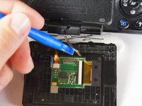
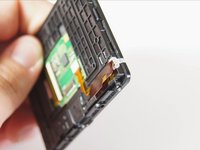
Use a plastic opening tool to disconnect the silver wires from the screen's circuitry and completely remove the screen from the camera.
Hi thank you for the post I have managed to do this. But unfortunately broken one of the multi connection wires as shown in your image 4 please can you suggest what are my options. Thanks
Hi I have broken one of the wire from the metal looking connector. As shown in the step 4 image. Could you suggest me my options. Thank you. Hope fully not replace the camera
How do you open the plastic cover holding the lcd screen itself after ? It seems sealed :(
-
-
-
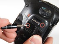
Unscrew the four 4.0 mm Phillips #00 screws with a on the base of the camera below the the scheme that separates the front and back panels.
-
Unscrew the 5.0 mm Phillips #00 screw on the bottom right of the camera.
-
-
-
Unscrew the 4.0 mm Phillips #00 screw on bottom of the left side of the camera.
-
Unscrew the 5.0 mm Phillips #00 screw near the top of the left side of the camera.
-
-
-
-
Unscrew the two 4.0 mm Phillips #00 screw at the top of the camera by the eyepiece.
-
Unscrew the 5.0 mm Phillips #00 screw of the dial below the other two screws.
-
Once all the screws are removed, carefully use your hands to detach the back panel from the camera. Working around the edges can help as well.
-
-
-
Remove the two 4.0 mm Phillips #00 screws on the right of the camera that are located on the upper right side and under the "Remote" port flap.
-
Detach the right side panel with the remote and HDMI ports of the camera by gently pulling on the panel.
-
-
crwdns2935267:0crwdne2935267:0Tweezers$4.99
-
Use tweezers to remove the blue and orange ribbon connectors from their connection points pictured here.
-
-
-
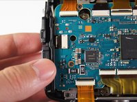
Remove the four 3.0 mm Phillips #00 screws.
-
Remove the 5.0 mm Phillips #00 screw.
-
-
crwdns2935267:0crwdne2935267:0Tweezers$4.99
-
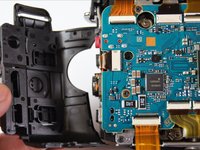
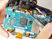
Use your finger to flip the switch that holds the dual ribbon connector in place.
-
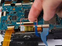
Gently use tweezers to disconnect the dual ribbon connector and the thin blue ribbon connector to the right of it from the circuit board.
-
-
-
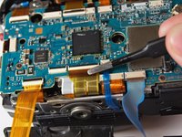
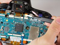
Use tweezers to disconnect the blue, gold, and brown ribbon connectors near the top of the camera.
-
-
-
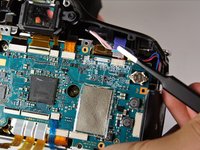
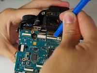
Use a plastic opening tool to pop open the connector holding the next ribbon to the circuit board.
-
Use tweezers to disconnect the ribbon.
-
-
-
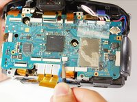
Use tweezers to unplug the blue adapter located at the top right of the circuit board.
-
-
-
Use either plastic opening tools or tweezers to unplug the white adapter located on the right side of the circuit board.
-
-
-
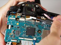
Gently lift the circuit board away from the camera and turn it over.
-
Use tweezers to disconnect the final two plugs and completely remove the circuit board from the camera.
-


To reassemble your device, follow these instructions in reverse order.
To reassemble your device, follow these instructions in reverse order.
crwdns2935221:0crwdne2935221:0
crwdns2935229:012crwdne2935229:0
crwdns2915084:0crwdne2915084:0

Cal Poly, Team 14-11, Amido Spring 2015 crwdns2935289:0Cal Poly, Team 14-11, Amido Spring 2015crwdne2935289:0
CPSU-AMIDO-S15S14G11
crwdns2931471:04crwdne2931471:0
crwdns2935297:013crwdne2935297:0
crwdns2947412:05crwdne2947412:0
I posted this link to a "Can't read SD card problem" below. On most SLTmodels apparently the SD card reader is part of the main circuit, and my local repair shop wanted $160 for labor (!) to swap out the part:
does anyone know if replacing the motherboard would fix a fried aperture lever control motor?
My camera will not read SD cards and intermittent struggles with lens connections. I sent it out for repair and the response was as follows: “AM main board would need to be replaced and is no longer available.” Is the AM main board another name for the Mother Board?
Does any know can i buy the flex cable for view finder button?
Thank you for all these Fixit helps. I am missing the replacement of the shutter motor. This is the most important repair in my eyes.