crwdns2915892:0crwdne2915892:0
The motherboard is the brains of the camera. Replacing the motherboard requires completely opening up the camera.
crwdns2942213:0crwdne2942213:0
-
-
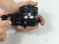
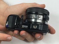
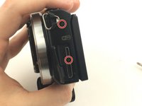
Open the battery compartment by sliding the lock to the right.
-
-
-
Begin by holding the camera upside down with the bottom facing you. Identify the housing for the SD card, and battery.
-
You will use your other hand to slide the lock switch to this housing to the right. This will release the cap, allow it to come upwards.
-
-
-
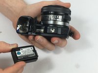
Now that the cap to the battery and SD card housing is open, the SD card is visible.
-
You will need to press down on the SD card until you hear a click. Release the SD card and it will now be available to remove.
-
Grip the SD card and pull it out of the SD card slot.
-
-
-
To reinsert the SD card place it in its housing.
-
You will then need to push down on the SD card until you hear a click.
-
-
-
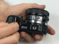
You may now close the housing for the SD card and battery.
-
Close the cap and while holding it down slide the locking tab to the left. This step should lock the cap in place.
-
-
-
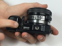
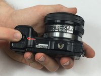
Remove the 3.5 mm exterior-side screw.
-
-
-
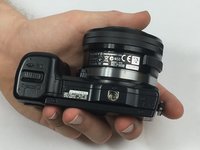
Remove the 3.5 mm bottom screw from the battery compartment.
-
-
-
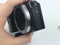
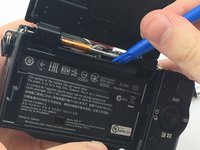
Pry off the front-side cover with the small plastic spudger.
-
-
-
-
Open the USB cover on the side of the camera.
-
Remove the 3.5 mm USB side screws.
-
-
-
Remove the 4mm screws at the back of the battery compartment.
-
-
-
Remove the 3.5 mm top flash-mount screw.
-
-
-
Flip the screen up.
-
Pry the top cover off with the small plastic spudger.
-
-
-
Pry the top part rear cover off with plastic spudger.
-
Flip the camera so the sensor faces down and push up on the rear cover from the battery compartment.
-
-
-
Remove the 2.25 mm tripod mount screws.
-
-
-
Remove the 2.25 mm side lanyard mount screw.
-
Pull the lanyard mount to remove.
-
-
-
Remove the 2.25 mm screws from the top.
-
-
crwdns2935267:0crwdne2935267:0Tweezers$4.99
-
Using the tweezers, pull out the rubber grommet.
-
-
-
Pull the lead that was under the grommet out from the frame.
-
-
-
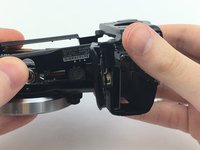
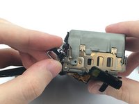
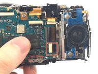
Flip the rotary selector and controls up over the top.
-
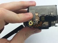
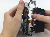
Holding the controls in place, pull the two frame pieces apart.
-
-
-
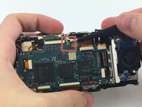
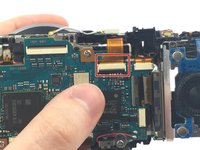
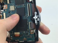
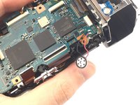
Disconnect the connection between the motherboard and LCD screen by pulling out the connector in the direction of the arrow.
-
-
-
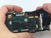
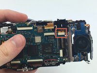
Using the tweezers, disconnect the metal lead at the top of the motherboard by pulling up.
-
-
-
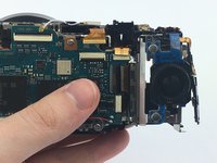
Disconnect the two top-right connectors by pulling them up towards the top.
-
-
-
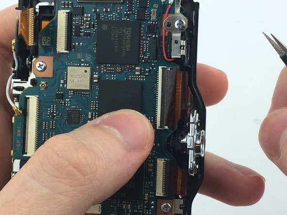
Disconnect the two connectors on the right by pulling them to the right.
-
-
-
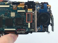
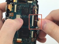
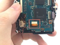
Using the tweezers, flip open the black door on the large connector on the bottom.
-
Remove the connector by pulling it away from the motherboard.
-
-
-
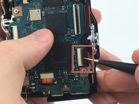
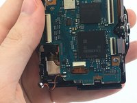
Using the tweezers, flip open the door on the smaller connector.
-
Remove the connector by pulling it away from the motherboard.
-
-
-
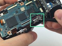
Disconnect the connector that goes through the motherboard.
-
-
-
Remove the 4 mm screws securing the motherboard to the frame.
-
-
-
With the tweezers, remove the metal speaker cover.
-
Pull the speaker out of the frame.
-
-
-
Flip the motherboard up and disconnect the connector on the back.
-
Seperate the motherboard from the frame.
-


To reassemble your device, follow these instructions in reverse order.
To reassemble your device, follow these instructions in reverse order.
crwdns2915084:0crwdne2915084:0

USF Tampa, Team S13-G2, Cagle Spring 2017 crwdns2935289:0USF Tampa, Team S13-G2, Cagle Spring 2017crwdne2935289:0
USFT-CAGLE-S17S13G2
crwdns2931471:03crwdne2931471:0
crwdns2935297:012crwdne2935297:0