crwdns2915892:0crwdne2915892:0
Removing the LCD will be moderately difficult. Be careful to not damage any ribbons when removing them from their sockets.
crwdns2942213:0crwdne2942213:0
-
-
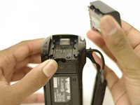
Rotate your camera such that the underside is facing you and the lens is facing the ground.
-
-
-
Using your left thumb, push down the slider to the left of the SD card slot.
-
-
-
Using your right index finger and thumb, pull the battery toward you and then away from the camera.
-
-
-
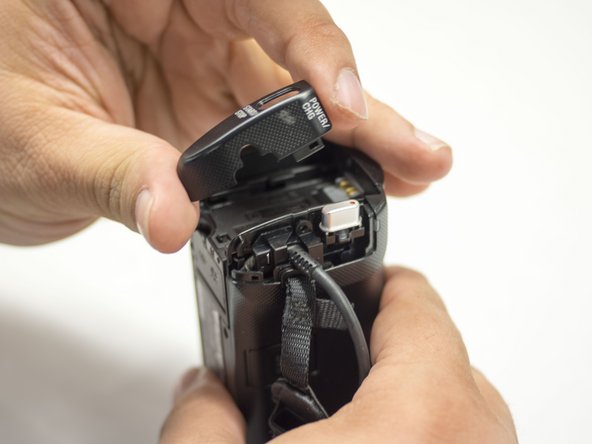
Orient the camera with the battery side facing up.
-
-
-
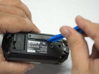
Remove the single 4.5 mm Phillips #00 screw.
-
Remove the single 5.5 mm Phillips #00 screw.
-
-
-
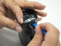
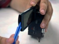
With the blue plastic opening tools, gently pry the plastic casing surrounding the start/stop button free.
-
Remove the casing using your right thumb and index finger.
-
-
-
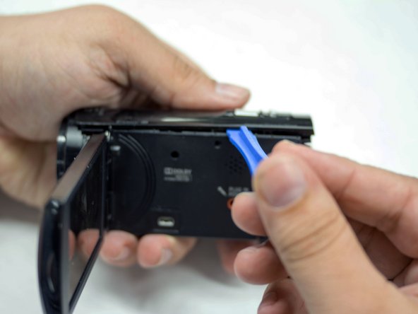
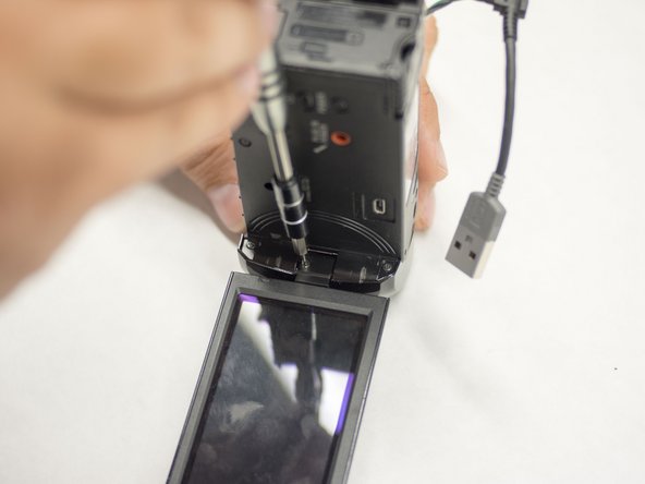
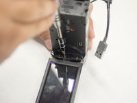
Flip open the LCD panel to get to the side panel.
-
Remove the three 5.5 mm Phillips #00 screws.
-
-
-
Turn the camera around to the grip side and remove the 5.5 mm Phillips Head screw using your J00 Phillips Head screwdriver.
-
-
-
With the bottom of the camera facing up, remove the two 5.5mm Phillips #00 screws.
-
-
-
Orient the camera so the bottom is facing you.
-
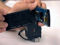
Use the blue plastic opening tools to gently ease the camera shell off of the camera.
-
Rotate the camera so the LCD side panel is facing you and gently pry the shell off from the camera.
-
-
-
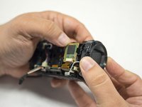
Orient the camera such that the lens is facing to your left.
-
Using your right hand to hold the camera, gently remove the lens panel from the camera with your left hand.
-
-
-
Rotate the camera so that it is upright and the lens is pointed to your left.
-
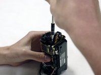
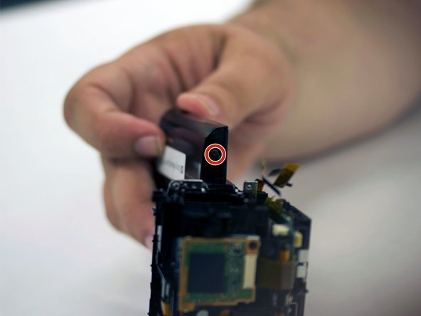
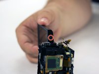
Using your right hand to hold the screwdriver and your left to hold the camera, remove the single 5.5 mm Phillips #00 screw from on the top of the shutter assembly.
-
-
-
-
Rotate the camera such that the lens is pointed downward and the LCD screen points to your right.
-
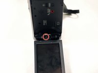
Remove the two Phillips #00 screws from the LCD screen's hinge.
-
-
-
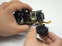
Orient the camera such that it is upright and the lens is facing to your right.
-
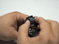
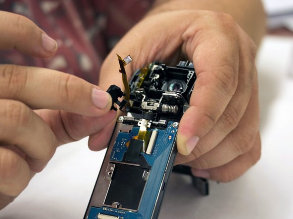
Using your left hand to hold the camera, gently remove the shutter assembly from the hull with your right hand.
-
-
crwdns2935267:0crwdne2935267:0Tweezers$4.99
-
Orient the camera such that the bottom is facing toward you and the lens is facing to your right.
-
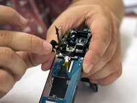
Using your metal tweezers, gently remove the wire harness connecting the shutter assembly to the motherboard.
-
-
-
Rotate the camera so that it is upright and the lens is facing to your right.
-
Remove the ribbon cable connecting the shutter assembly to the motherboard using your metal tweezers.
-
-
-
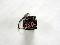
Remove the three 5.5mm Phillips #00 screws holding the lens in.
-
-
-
Gently pull the lens up from the camera.
-
-
-
With the right side of the camera facing toward you, remove the single 5.5 mm Phillips #00 screw.
-
-
-
With the back of the LCD screen facing toward you, remove the two 5.5 mm Phillips #00 screws from the zoom button.
-
-
-
Orienting the camera such that the right side is facing you, remove the single 5.5 mm Phillips #00 screw from the start button.
-
-
-
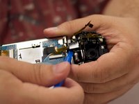
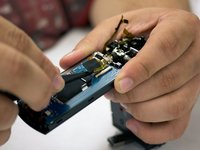
Use your blue plastic opening tool to disconnect the lens assembly from the hull.
-
-
-
Use your blue plastic opening tool to move the wires out of the way.
-
-
crwdns2935267:0crwdne2935267:0Tweezers$4.99
-
Orienting the camera such that the right side is facing you, remove the wire harness connecting the lens assembly to the motherboard using your tweezers.
-
-
-
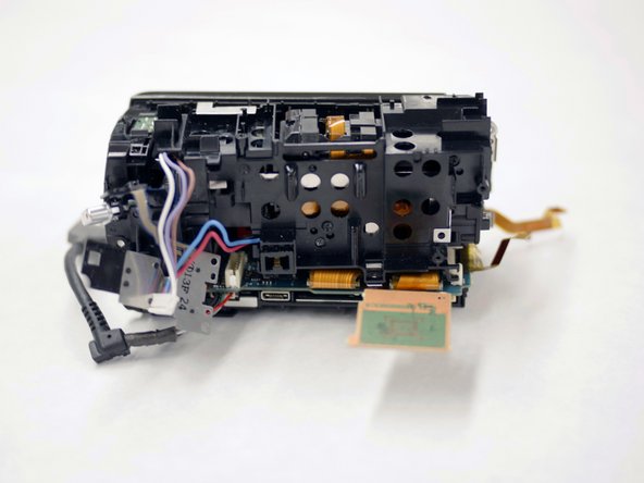
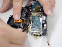
Pull the lens assembly out from inside the camera's hull using your hands.
-
-
-
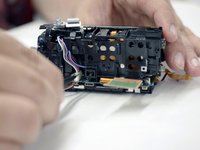
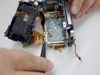
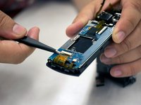
Orienting the camera such that the front side is facing you, remove the ribbon connecting the start and zoom buttons to the powerboard using your tweezers.
-
-
-
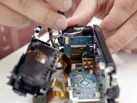
Using your tweezers, remove the two ribbon cables connecting the lens assembly to the motherboard.
-
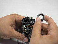
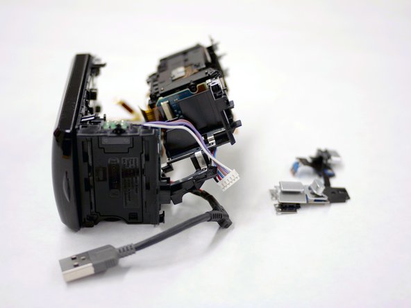
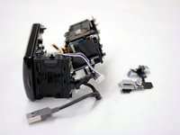
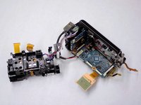
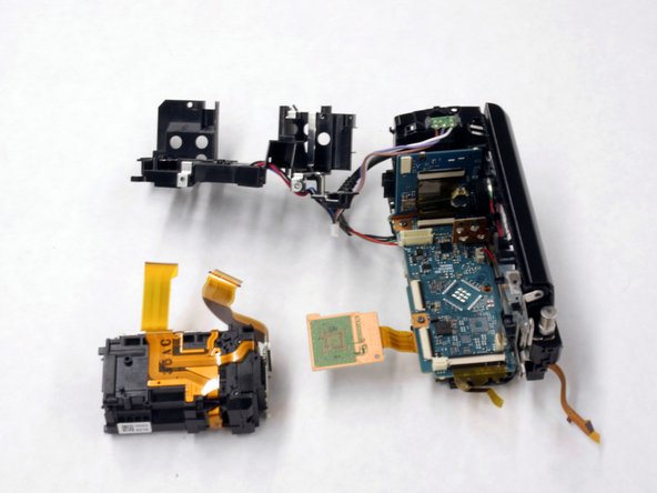
The lens assembly casing should now be free. Remove it from the hull of the camera.
-
-
-
Remove the two 4.5 mm Phillips #000 screws connecting the lens assembly to its casing.
-
The lens assembly is now completely free. Remove it from its casing.
-
-
-
Rotate the LCD screen on its hinge +/- 90 degrees relative to the camera to expose the screws on the side of the LCD panel.
-
Remove the two 5.5 mm Phillips #00 screws.
-
-
-
Remove the single 3 mm Phillips #00 screw from inside of the hinge of the LCD panel.
-
-
-
Using the plastic opening tools , remove the back panel from the LCD screen.
-
-
-
Remove the hinge enclosure from the back of the LCD screen using the blue plastic opening tools.
-
-
crwdns2935267:0crwdne2935267:0Tweezers$4.99
-
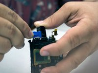
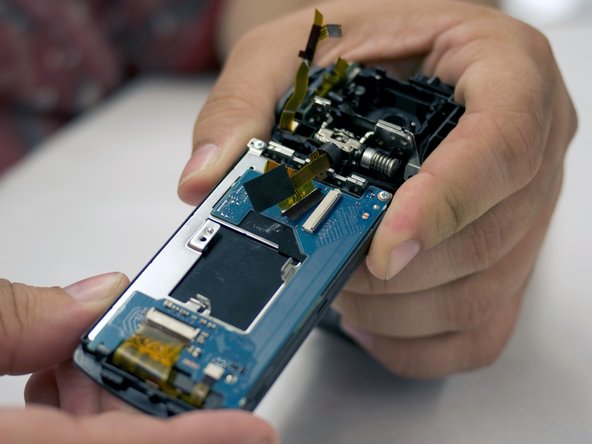
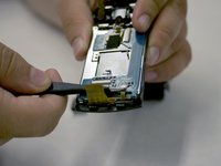
With tweezers, remove the ribbon cable that is connecting the LCD screen board to the motherboard.
-
-
-
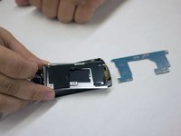
Using metal tweezers, remove the two ribbons connecting the LCD board to the screen.
-
-
-
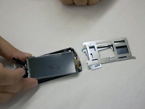
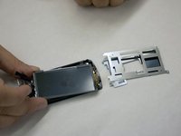
Remove the two silver-colored 4.5 mm Phillips #00 screws from LCD board.
-
-
-
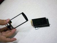
The LCD screen and all of its components are free. Unravel them and replace parts as needed (main board, screen, metal fixture, etc.)
-


To reassemble your device, follow these instructions in reverse order.
crwdns2935221:0crwdne2935221:0
crwdns2935229:03crwdne2935229:0
crwdns2935287:0crwdne2935287:0

USF Tampa, Team 16-5, Blackwell Winter 2016 crwdns2935289:0USF Tampa, Team 16-5, Blackwell Winter 2016crwdne2935289:0
USFT-BLACKWELL-W16S16G5
crwdns2931471:03crwdne2931471:0
crwdns2935297:016crwdne2935297:0