crwdns2915892:0crwdne2915892:0
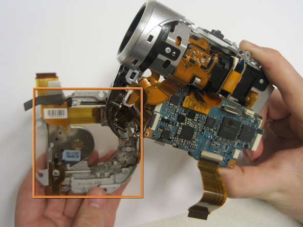
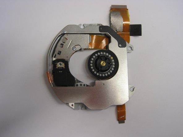
Occasionally, the laser eye will break or no longer move along the track. In this handycam, the laser eye is not replaceable by itself, but the laser bay may be swapped.
crwdns2942213:0crwdne2942213:0
-
-
Turn the camera so the back side, beneath the viewfinder, is facing you.
-
Locate the battery pack compartment.
-
Press the small release button near the battery compartment.
-
While pressing the button, slide the switch forward to unlock the battery.
-
-
-
Carefully pull the battery pack out of the compartment.
-
To reinsert, align the battery pack with the compartment.
-
Slide the battery back into the camera until it clicks securely into place..
-
-
-
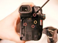
Using a #00 Phillips screwdriver, remove the six 4.5 mm screws from the camera's bottom.
-
-
-
Remove the three 4.5 mm screws beneath the battery.
-
Remove the 2.9 mm screw from the right corner.
-
Remove the two 4.5 mm screws from the battery's right wall.
-
-
-
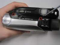
Remove the 4.5 mm screw under the output flap on the front of the camera below the lens.
-
-
-
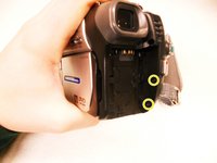
Remove the two 4.5 mm screws at the top of the camera.
-
Remove the 4.5 mm screw from the disk side of the camera (next to the lens).
-
-
-
-
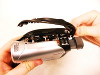
Extend the gray viewfinder, then gently remove the black plastic casing.
-
-
-
Remove the two 2.9 mm screws under the black plastic casing.
-
-
-
Gently pull apart the outer silver case and screen.
-
Remove the copper wire strip to detach the case from the camera.
-
-
-
Remove (1) 2.9mm screw from under the eye piece.
-
Remove (1) 2.9mm screw from above the eye piece.
-
Remove (4) copper strips from bellow the eye piece.
-
Pull off the eye piece assembly.
-
-
-
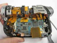
Pull off back cover. Caution: Be careful not to tear any copper strips in the process.
-
Remove (4) copper strips in order to pull off eye piece.
-
-
-
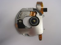
Remove (4) 3.6mm wide head screws on the laser reader.
-
-
-
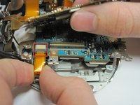
Unplug copper strip and lift up.
-
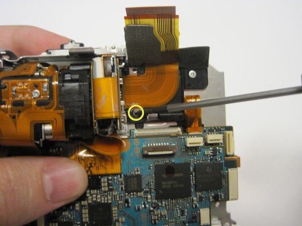
Pull off tape over 2.3mm screw.
-
Remove (1) 2.3mm screw from under the tape.
-
-
-
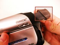
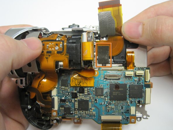
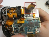
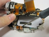
Pull the copper strip, marked by the red rectangle, through the hole behind it, marked with the yellow rectangle.
-
-
-
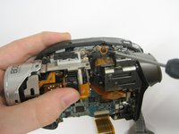
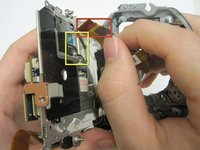
Remove (3) 2.9mm screws from top circuit board.
-
Lift up circuit board and remove (1) 2.9mm screw underneath.
-
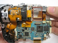
Pull out copper plate with rubber insulator on it.
-
-
-
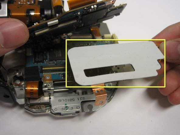
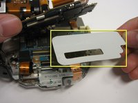
Remove tape over copper strip in the bottom left corner and pull out copper strip.
-
Remove laser reader assembly.
-


To reassemble your device, follow these instructions in reverse order.
crwdns2935221:0crwdne2935221:0
crwdns2935227:0crwdne2935227:0
crwdns2935287:0crwdne2935287:0

Cal Poly, Team 7-44, Regan Winter 2011 crwdns2935289:0Cal Poly, Team 7-44, Regan Winter 2011crwdne2935289:0
CPSU-REGAN-W11S7G44
crwdns2931471:05crwdne2931471:0
crwdns2935297:010crwdne2935297:0