crwdns2942213:0crwdne2942213:0
-
-
Remove battery by sliding the tab to open the cover
-
-
-
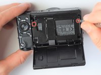
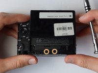
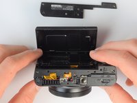
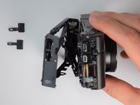
Using the screwdriver, remove all screws (black 2.5mm) from outermost layer of the assembly.
-
-
-
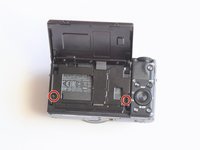
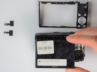
Also using the screwdriver, remove screws (black 1mm) underneath articulated LCD screen.
-
Remove the marked 2.5 mm screws with the screwdriver
-
-
-
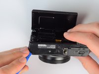
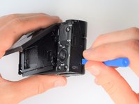
Using the plastic opening tools, carefully pry off the bottom plate.
-
-
-
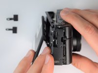
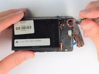
Using the same plastic opening tools, separate the screen and back assembly from the front portion of the camera
-
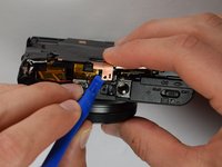
Once the back assembly is slightly detached, pull the media covers for the HDMI and Multimedia ports
-
-
-
-
Move side panel to get access to screws
-
Remove two screws (black 2.5mm) with PH #0 screwdriver
-
-
-
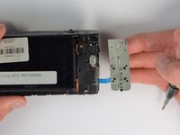
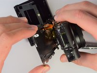
Remove back panel assembly while still keeping ribbon cable attached
-
-
-
Carefully unplug ribbon connector to fully detach LCD screen assembly from camera
-
-
-
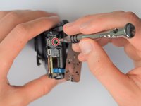
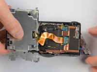
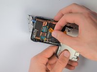
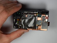
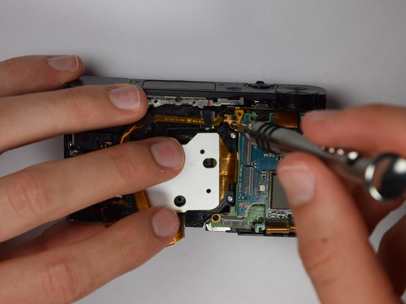
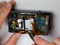
Remove remaining screw which holds the copper casing in the camera
-
-
-
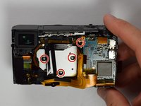
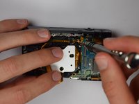
Using the plastic opening tools, carefully pry off the copper casing at the two pictured points.
-
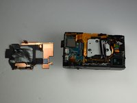
Remove casing
-
-
-
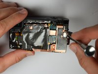
Using Philips Screwdriver, remove the four screws as marked on the picture
-
-
-
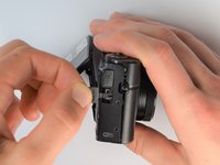
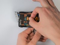
Place your finger into the battery port and push up on the SD card holder to push it out of its socket.
-
-
crwdns2935267:0crwdne2935267:0Tweezers$4.99
-
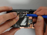
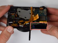
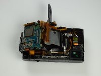
Carefully remove the gold ribbons from the ports of the motherboard by lifting the gray tabs and pulling away the ribbon
-
You may want to use tweezers to remove the gold ribbons as a more delicate and safe approach, but this is not required
-
-
-
Remove the SD card holder. It should easily come out because all of the prerequisite screws were already removed.
-
-
-
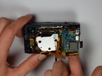
Carefully remove the last gold ribbon by lifting the gray tab and sliding out the ribbon.
-
-
-
Viola! The motherboard is now removed and can be replaced with a new one.
-


To reassemble your device, follow these instructions in reverse order.
To reassemble your device, follow these instructions in reverse order.
crwdns2935221:0crwdne2935221:0
crwdns2935229:04crwdne2935229:0
crwdns2915084:0crwdne2915084:0

Cal Poly, Team 21-1, Maness Winter 2017 crwdns2935289:0Cal Poly, Team 21-1, Maness Winter 2017crwdne2935289:0
CPSU-MANESS-W17S21G1
crwdns2931471:05crwdne2931471:0
crwdns2935297:010crwdne2935297:0