crwdns2942213:0crwdne2942213:0
-
-
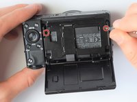
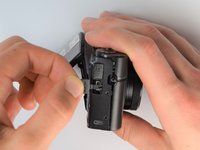
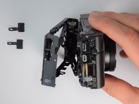
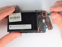
Remove battery by sliding the tab to open the cover
-
-
-
Using the screwdriver, remove all screws (black 2.5mm) from outermost layer of the assembly.
Split this step up into multiple steps based on where screws are being removed from or specify how many screws are removed in this step
-
-
-
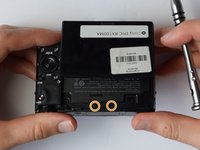
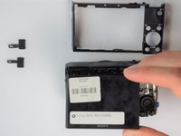
Also using the screwdriver, remove screws (black 1mm) underneath articulated LCD screen.
-
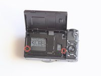
Remove the marked 2.5 mm screws with the screwdriver
2 different types of screws are removed in this step: specify the types
It is not necessary to remove the hinge screws. It is much easier to remove the back panel with the LCD still attached and not flopping about everywhere.
-
-
-
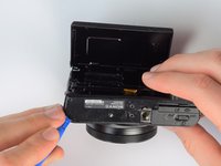
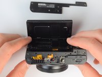
Using the plastic opening tools, carefully pry off the bottom plate.
-
-
-
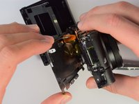
Using the same plastic opening tools, separate the screen and back assembly from the front portion of the camera
-
Once the back assembly is slightly detached, pull the media covers for the HDMI and Multimedia ports
-
-
-
-
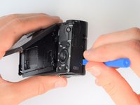
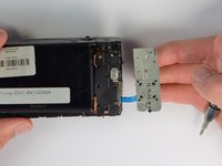
Move side panel to get access to screws
-
Remove two screws (black 2.5mm) with PH #0 screwdriver
In the second picture of the side, it is not the upper screw by the USB that needs removing, but the lower one by the SD/battery door
-
-
-
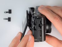
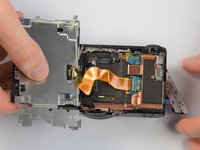
Remove back panel assembly while still keeping ribbon cable attached
-
-
-
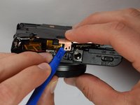
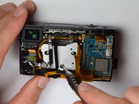
Carefully unplug ribbon connector to fully detach LCD screen assembly from camera
It is worth saying that the grey line on the left-hand edge of the flex connector flips up to release the flex.
-
-
-
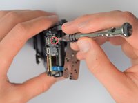
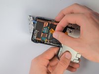
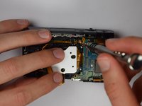
Remove remaining screw which holds the copper casing in the camera
-
-
-
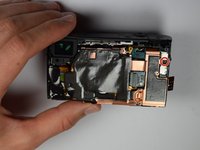
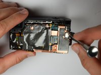
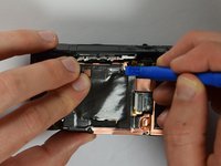
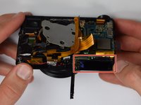
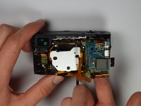
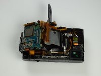
Using the plastic opening tools, carefully pry off the copper casing at the two pictured points.
-
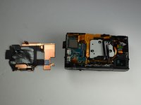
Remove casing
I still have two black glued maybe cables above the copper board. Can't find them in the description but they are already missing in your picture of step 10.
The connector next to the display connector is unplugged in the last picture of step 11 but not mentioned in the text.
-
-
-
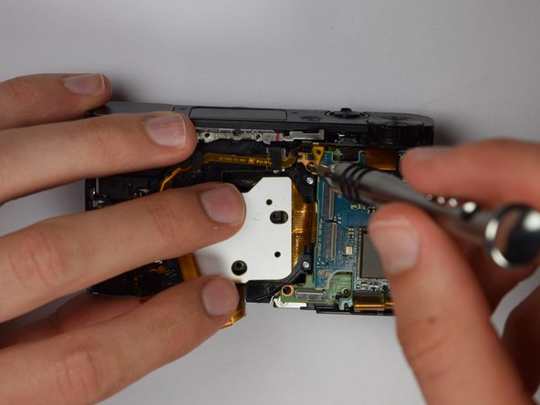
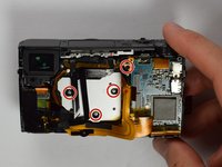
Using Philips Screwdriver, remove the four screws as marked on the picture
-
-
-
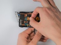
Place your finger into the battery port and push up on the SD card holder to push it out of its socket.
Warning Take care because at this stage the senor chip will become exposed to contamination. the grey plate is its heatsink.
The small cover of the HDMI port was removed here as well.
-
-
crwdns2935267:0crwdne2935267:0Tweezers$4.99
-
Carefully remove the gold ribbons from the ports of the motherboard by lifting the gray tabs and pulling away the ribbon
-
You may want to use tweezers to remove the gold ribbons as a more delicate and safe approach, but this is not required
-
-
-
Remove the SD card holder. It should easily come out because all of the prerequisite screws were already removed.
-


To reassemble your device, follow these instructions in reverse order.
To reassemble your device, follow these instructions in reverse order.
crwdns2915084:0crwdne2915084:0

Cal Poly, Team 21-1, Maness Winter 2017 crwdns2935289:0Cal Poly, Team 21-1, Maness Winter 2017crwdne2935289:0
CPSU-MANESS-W17S21G1
crwdns2931471:05crwdne2931471:0
crwdns2935297:010crwdne2935297:0
crwdns2947410:01crwdne2947410:0
Dear Isaiah De Leon !
I have a Sony RX 100 Mk4, and it is out of order. :(
First just the digital zoom button (up on the camera) didn't work
Later the manual zoom (lens ring moving) didn't work
Now the rest of the marked buttons does not work.
(Sometimes yes, but usually no funcion at all)
The camera was handled care, didn't fall down, no water contact!
Sony service says, no physical problem, they advise the panel to be replaced. (It is about 120€ + 60€ working fee)
Some Sony fan member advised “the little cable just under dial there that connects all the controls has slowly slipped out. “ could be the problem,
Could You please send a picture which cable can it be, or please any other advice.
Thanks!!!
Ádám
berkesi.adam@gmail.com