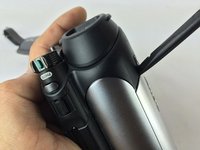
crwdns2915892:0crwdne2915892:0
The motherboard paramount for the proper function of the camera, basically acting like a "brain." This guide will serve as check for electronic connections, and a full removal procedure of this critical component.
crwdns2942213:0crwdne2942213:0
-
-
Remove all the 4.3mm screws on the bottom using a J000 Phillips screwdriver. There should be seven screws (4 silver, 2 black).
-
-
-
Remove the 5mm #0 Phillips screws on the underside of the LCD tuck-a-way.
-
-
-
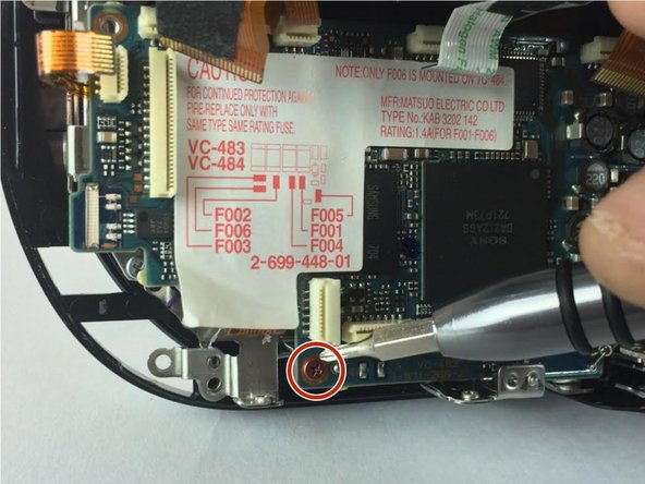
Remove the 2mm #0 Phillips screw behind the battery.
-
-
-
-
Open the dvd cover and remove the 3 4.3mm phillips screws. Including ones in the corners that may be hidden.
-
-
-
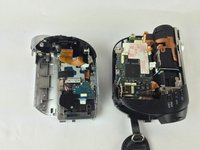
Once all the screws are removed you can safely pry open the camera case using a spudger.
-
-
crwdns2935267:0crwdne2935267:0Tweezers$4.99
-
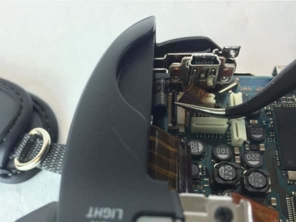
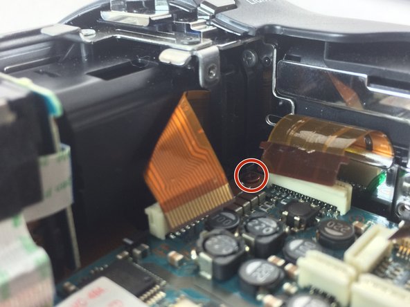
Remove all ribbon connectors from the motherboard using tweezers. Simply grab each ribbon cable and pull straight out of the connector.
-
There is a hidden wire on the bottom of the board that should also be removed.
-
-
-
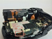
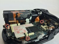
Remove 3 brown copper screws. Each copper screw has a #0 Phillips head and is 2.8mm in length.
-
-
-
Lift the motherboard up from the outside edges to remove.
-


In order to reassemble your device, follow these instructions in reverse order.
crwdns2935221:0crwdne2935221:0
crwdns2935229:02crwdne2935229:0

crwdns2935287:0crwdne2935287:0

USF Tampa, Team 7-6, Cheng Spring 2016 crwdns2935289:0USF Tampa, Team 7-6, Cheng Spring 2016crwdne2935289:0
USFT-CHENG-S16S7G6
crwdns2931471:03crwdne2931471:0
crwdns2935297:010crwdne2935297:0