crwdns2933423:0crwdne2933423:0

Sony Cyber-shot DSC-HX90V Motherboard Replacement

crwdns2942213:0crwdne2942213:0

  1. Sony Cyber-shot DSC-HX90V Motherboard Replacement, Button board: crwdns2935265:01crwdnd2935265:01crwdnd2935265:01crwdne2935265:0
    • Place the device so bottom of the camera is facing up .

    • Remove the five black M1.4 X 3.5 Phillips head screws with a Phillips #000 screwdriver.

  2. Sony Cyber-shot DSC-HX90V Motherboard Replacement: crwdns2935265:02crwdnd2935265:01crwdnd2935265:01crwdne2935265:0
    • Remove the marked black M1.4 X 3.5 Phillips head screws on the side of the camera with a Phillips #000 screwdriver.

  3. Sony Cyber-shot DSC-HX90V Motherboard Replacement: crwdns2935265:03crwdnd2935265:01crwdnd2935265:01crwdne2935265:0
    • Remove the marked screw with a Phillips #000 screwdriver.

  4. Sony Cyber-shot DSC-HX90V Motherboard Replacement: crwdns2935265:04crwdnd2935265:01crwdnd2935265:02crwdne2935265:0 Sony Cyber-shot DSC-HX90V Motherboard Replacement: crwdns2935265:04crwdnd2935265:02crwdnd2935265:02crwdne2935265:0
    • Use the plastic opening tool to remove the button board.

  5. Sony Cyber-shot DSC-HX90V Motherboard Replacement: crwdns2935265:05crwdnd2935265:01crwdnd2935265:02crwdne2935265:0 Sony Cyber-shot DSC-HX90V Motherboard Replacement: crwdns2935265:05crwdnd2935265:02crwdnd2935265:02crwdne2935265:0
    • Disconnect the control board data cable with care. Permanent damage may occur to the control board if tools are used to disconnect the data cable. Use your fingers only.

    • Disconnect the control board data cable by wiggling carefully with your fingertips. Set the control board to the side once it is disconnected.

  6. Sony Cyber-shot DSC-HX90V Motherboard Replacement, Side cover: crwdns2935265:06crwdnd2935265:01crwdnd2935265:01crwdne2935265:0
    • Use the plastic opening tool with a prying motion to remove the side cover of the camera.

    • The cover should come off easily but you might hear light snapping or popping.

  7. Sony Cyber-shot DSC-HX90V Motherboard Replacement, LCD: crwdns2935265:07crwdnd2935265:01crwdnd2935265:01crwdne2935265:0
    • Orient the device so the lens is facing down.

    • Remove the two black M1.4 X 3.5 Phillips head screws using Phillips #000 screwdriver.

  8. Sony Cyber-shot DSC-HX90V Motherboard Replacement: crwdns2935265:08crwdnd2935265:01crwdnd2935265:01crwdne2935265:0
    • Orient the device so the lens is facing down.

    • Remove the black M1.4 X 3.5 Phillips head screw.

  9. Sony Cyber-shot DSC-HX90V Motherboard Replacement: crwdns2935265:09crwdnd2935265:01crwdnd2935265:02crwdne2935265:0 Sony Cyber-shot DSC-HX90V Motherboard Replacement: crwdns2935265:09crwdnd2935265:02crwdnd2935265:02crwdne2935265:0
    • LCD screen is very fragile. Handle with care. Do not use tools to remove the screen.

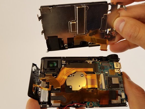
    • Remove the ribbon cable connecting LCD display to camera sensor and battery housing.

  10. Sony Cyber-shot DSC-HX90V Motherboard Replacement, Motherboard: crwdns2935265:010crwdnd2935265:01crwdnd2935265:01crwdne2935265:0
    • Make sure all ribbon cables are unplugged and remove the motherboard.

    • Ribbon wires can be easily damaged.

crwdns2915888:0crwdne2915888:0

To reassemble your device, follow these instructions in reverse order.

crwdns2935227:0crwdne2935227:0

Marin Rusinov

crwdns2935283:002/02/17crwdne2935283:0

853 crwdns2915208:0crwdne2915208:0

crwdns2935297:05crwdne2935297:0

crwdns2944067:02crwdne2944067:0

super Anleitung, trotz aller Vorsicht ist ein Flachbandkabel kaputt gegangen, und zwar das 2 adrige zu Sucher. Wie kann man Flachbandkabel reparieren oder ersetzen?

LG

Michael

Michael Bühnen - crwdns2934203:0crwdne2934203:0

Hello!

Nice help to open the camera for fixing viewfinder problems: when not switching on, even when FINDER/MONITOR mode on FINDER, there might be a bad contact in the visor connector. It is a snap lock micro connector, open the lock, then carefully remove clean and replace ribbon cable:this may clear the trouble.

But attention: At least on HX9O without V ext. there are some more screws ;-) and niceties

- one in step 3, under the MULTI connector cap

- 3 on different places to remove LCD screen

Also, there is also an antenna , connected to the LCD assembly and lightly glued on the side

Frantz Bernhard - crwdns2934203:0crwdne2934203:0

crwdns2917038:0crwdne2917038:0

crwdns2936625:0crwdne2936625:0:

crwdns2936751:024crwdne2936751:0 1

crwdns2936753:07crwdne2936753:0 14

crwdns2936753:030crwdne2936753:0 51

crwdns2942667:0crwdne2942667:0 3,057