crwdns2915892:0crwdne2915892:0
Complete replacement of the outer case requires complete dissassembly of the camera. This is a good time to replace other components if needed.
crwdns2942213:0crwdne2942213:0
-
-
Orient the device so the bottom is facing up, and the lens is facing you ("bottom view").
-
-
-
Remove these two black M1.4 X 3.5 Phillips head screws.
-
The third, unmarked screw does not need to be removed at this time.
-
-
-
Orient the device so the LCD is facing you, and the hdmi cover is facing up ("left view).
-
Remove these three black M1.4 X 3.5 Phillips head screws.
-
-
-
Orient the device with the Wifi/GPS logo facing up ("right view").
-
-
-
Use a prying motion and a plastic opening tool to pry the side panel up.
Pull the panel down there are 2 clips in the midtle be carefull not to brake them
Just prying doesn't do it. there are some clips which are really easy to break!
I think it needs to be slided down!
It is not clips but "hook" so to the mouvement should be at opposite direction on flash
I inserted an opening pick under the lower part of the panel (where it was loosest; at the left of the photo) and then inserted a jimmy along one side (at the top of the photo). Then I pushed the panel down from the top (at the right in the photo) and it popped off.
I Broke my two clips, will gluing them help put them back together?
-
-
-
After removing the panel, remove the two black M1.4 X 3.5 Phillips head screws.
-
-
-
Orient the device so that the LCD is facing you ("back view").
take car around Menu button area - rear cover could broke.
-
-
-
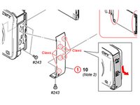
Use the plastic opening tool with a prying motion, going between the case and the LCD, from the middle of the LCD to the right of the device, undoing the claws retaining the back.
-
-
-
Unhook the small printed circuit board by gently pressing the board towards the top of the device and lifting up.
-
-
-
Using a plastic opening tool remove the black LCD retainer clip to the right of LCD.
-
-
-
Use the plastic opening tool to gently lift the LCD from the device
-
-
-
Using the plastic opening tool to lift the black retaining clip up to disengage the ribbon cable. Then gently pull the ribbon cable to remove.
when screen cable is plug, you can test before reassemble the device.
Help this is an urgent need please !!! I am stuck at step 12 : lifting the black retaining clip up just pops it out like a pop corn (tried several times) and then nothing moves :-(
No need to unplug the LCD, to take the lens
Il est inutile de débrancher l’écran LCD pour retirer l’objectif
-
-
-
-
Remove the black M1.4 X 3.5 Phillips head screw in upper right corner of the device.
-
Service manual for reference: Click to go to the service manual.
-
-
-
Reorient the camera so you are looking at the "top view".
-
Remove the black M1.4 X 3.5 Phillips head screw next to the ON/OFF button circled in red.
-
-
-
Orient the device so you are looking at the "bottom view".
-
Remove the black M1.4 X 3.5 Phillps head screw located next to the tripod attachment.
-
-
-
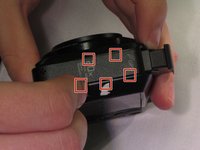
The connections (red squares) have small black retaining clips. Using a plastic opening tool, lift upward towards the cable to unlock.
-
The upper ribbon cable simply pulls loose.
-
-
-
Lift the lens block from the case.
Exactly with this very helpful description I have successfully changed my noisy lense system
thans a lot D. A. Waldvogel
-
-
-
Discharge the capacitor by connecting the resistor jig between the highlighted squares.
-
-
crwdns2935267:0crwdne2935267:0Tweezers$4.99
-
Use tweezers to remove the speaker retaining clip. The retaining hooks locations are indicated, but not exact.
-
-
-
Remove the speaker by desoldering its wires.
-
-
-
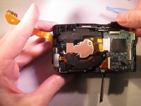
From the top of the camera, Use a plastic opening tool between the flash and the case to remove the flash.
-
-
-
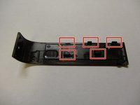
And here is the how the flash module should look after being removed.
-
This is a reference image: it is possible to further disassemble this module, and is not necessary.
-
-
-
Remove the black M1.4 X 3.5 Phillips head screw in upper right corner of device.
-
-
-
Reorient the camera so you are looking at the "top view".
-
Remove the black M1.4 X 3.5 Phillips head screw just below the ON/OFF button circled in red.
-
-
-
Orient the device so you are looking at the "bottom view".
-
Remove the black M1.4 X 3.5 Phillips head screw located next to the tripod attachment.
-
-
-
The connections (red squares) have small black retaining clips. Using a plastic opening tool, lift upward towards the cable to unlock.
-
After detaching retaining clips, gently lift to disconnect the ribbon cables.
-
-
-
Remove the orange M1.4 X 3.5 Phillips head screw located near the bottom of the camera.
-
-
-
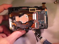
Lift up the motherboard.
-
Disconnect the ribbon cable on the bottom by gently pulling.
-
-
-
Remove these two silver M1.4 X 4.0 Philips head screws.
-
-
-
Using the plastic opening tool between the front edge of the camera and the top "control assembly", pry and unhook the claws roughly located in the red square.
-


To reassemble your device, follow these instructions in reverse order.
To reassemble your device, follow these instructions in reverse order.
crwdns2935221:0crwdne2935221:0
crwdns2935227:0crwdne2935227:0
crwdns2915084:0crwdne2915084:0

Eastern Washington University, Team 2-4, Matresse Spring 2015 crwdns2935289:0Eastern Washington University, Team 2-4, Matresse Spring 2015crwdne2935289:0
EWU-MATRESSE-S15S2G4
crwdns2931471:04crwdne2931471:0
crwdns2935297:010crwdne2935297:0
crwdns2947412:02crwdne2947412:0
can i follow the same instruction for SONY DSC HX 10V .as both looks identical . when i shake my camera sound comes as if some parts are loosen but when i switched on my camera and the lens comes out that sound goes off . should i care for it or not ?
Thank you! Useful instructions.
Step 5 - perhaps a little more accurate step would be to lift up the bottom of the panel and then slide the panel downward. (reinstall in reverse direction).
I am having trouble orienting the control wheel - I tried to seat the middle button so it clicks and then set down the wheel on top but that does not seem to work after putting the back cover on. I’ve reopened and tried many times. Any suggestions on how to orient or reinstall the control wheel.