crwdns2915892:0crwdne2915892:0
This guide is a follow up to start the process of actually replacing the top flex cable. I will try my best to guide you through with detailed steps & pictures.
crwdns2942213:0crwdne2942213:0
-
-
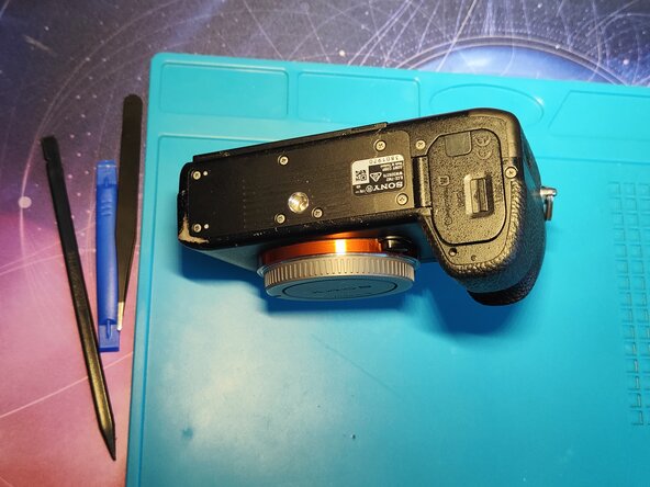
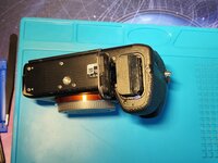
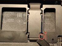
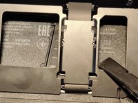
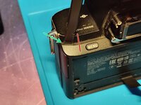
First start by removing the battery after opening the battery door via the blue lock thing.
-
Make sure to close it after removing the battery so you don't break it during the disassembly.
-
-
-
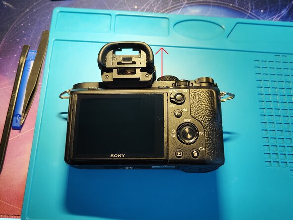
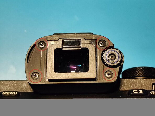
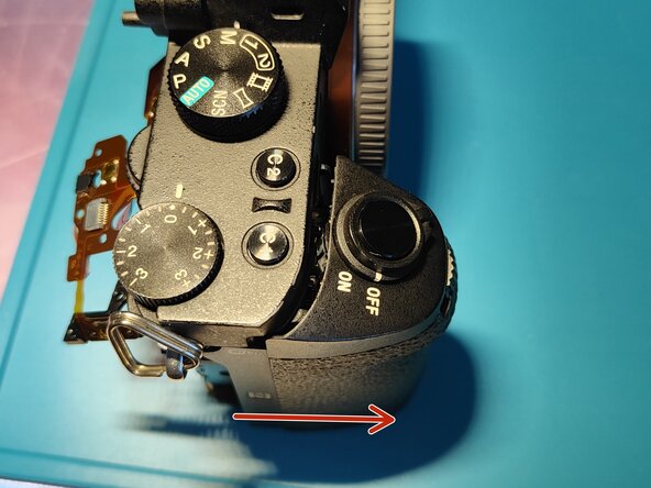
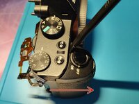
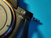
Remove the eye cup by sliding it away from you (see the arrow in the picture for the direction)
-
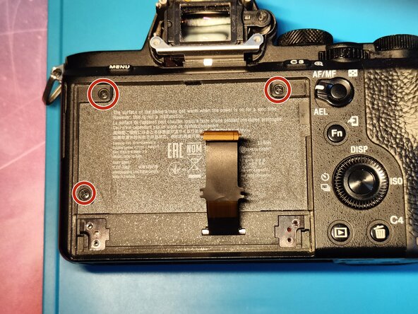
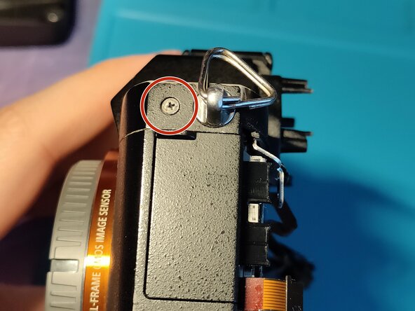
Remove the 5 screws with a P00 screwdriver (this is all you need during the whole disassembly, Sony was kind enough to only use P00 in the whole camera:))
-
The 4 screws marked with red circles are the same size, these are the smaller ones.
-
The one on the right marked with blue is a longer screw and it holds the diopter adjuster. Make sure not to lose it!
-
-
-
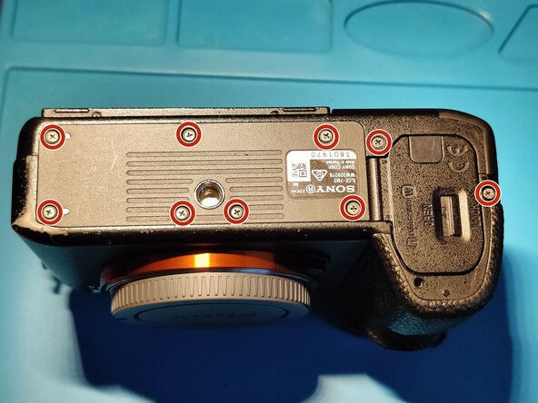
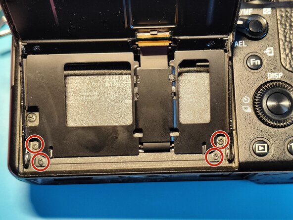
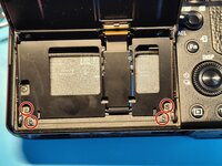
Remove all (9 in total) screws marked with red circles, they are all the same.
-
Note: In the next few steps there will be screws, which are the same as these marked ones. It will be written in the guide later on that "These are the same screws shown in Step 3.".
-
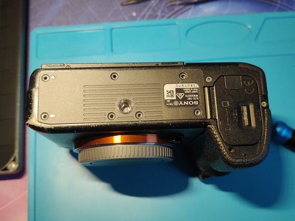
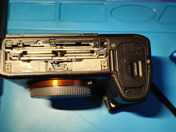
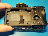
Remove the bottom plate.
-
-
-
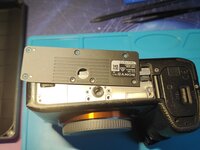
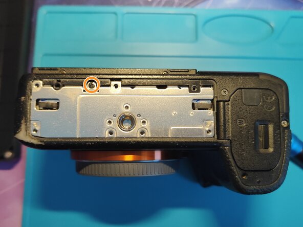
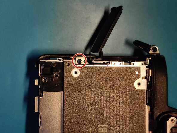
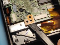
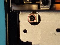
Remove one tiny screw marked with an orange circle.
-
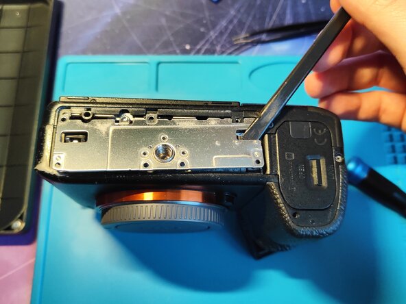
Remove the screw first and then gently pry under the plate. If the screw falls down, it will probably be caught by the IBIS' magnet - which takes a ton of time to remove.
-
Put the plate aside.
-
-
-
Remove the screws (3 in total) marked with red circles with a P00 screwdriver. These are the same screws shown in Step 3.
-
More in depth steps:
-
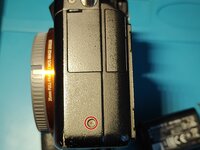
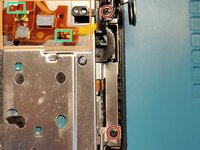
First remove one screw on the left side of the camera marked with a red circle.
-
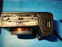
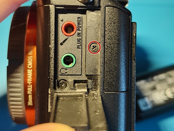
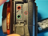
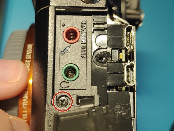
Gently open the plastic door covering the microphone and headphone inputs and remove one screw marked with a red circle. Gently close the plastic door.
-
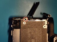
Lastly remove one screw on the right side of the camera marked with a red circle.
-
-
-
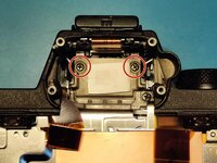
Remove the 2 different screws with a P00 screwdriver.
-
The one marked with red is a shorter black one.
-
The one marked with orange is a longer silver one.
-
-
-
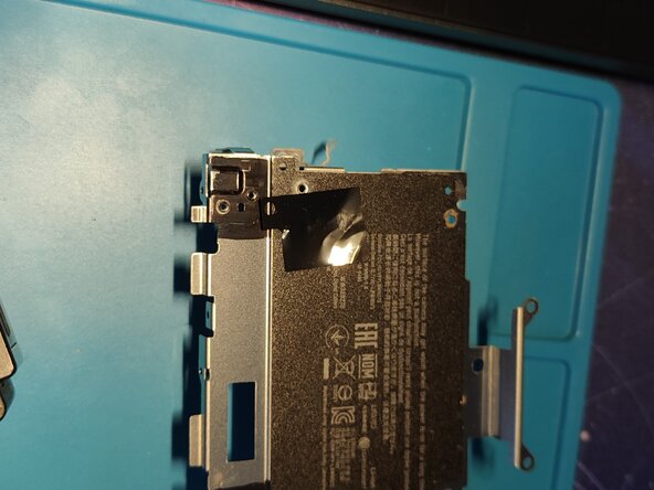
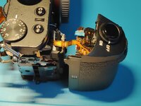
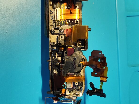
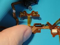
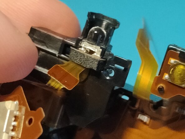
Open the screen fully (90 degrees) and put the camera screen facing the ceiling.
-
Gently apply pressure to the marked location on Picture 2 with a prying tool as shown (or anything else that might work) in the direction of the arrow.
-
Remove the shield that popped out of place.
-
Note: During reassembly try to line those little "feet" with the holes you pushed it out from, make sure those little tabs line up as before. Then push it in carefully in place.
-
-
-
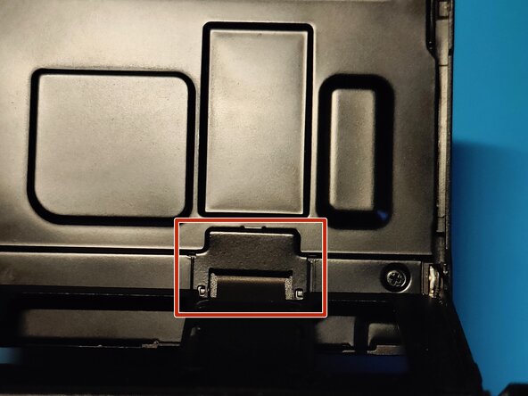
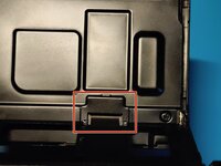
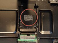
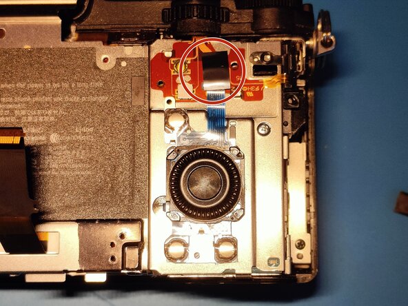
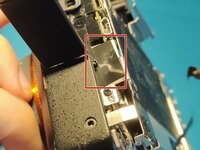
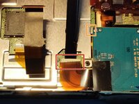
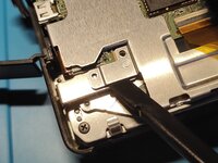
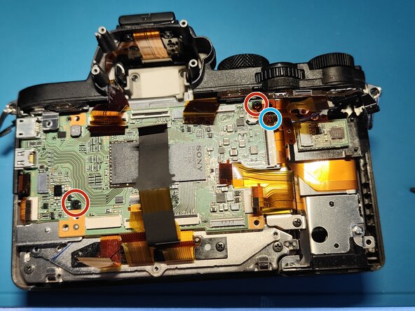
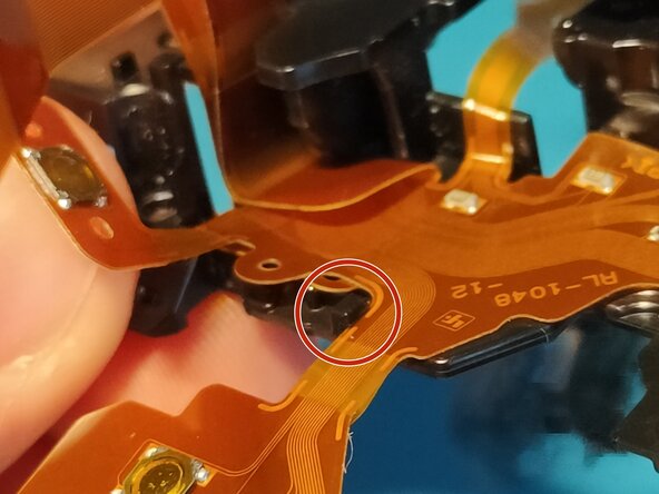
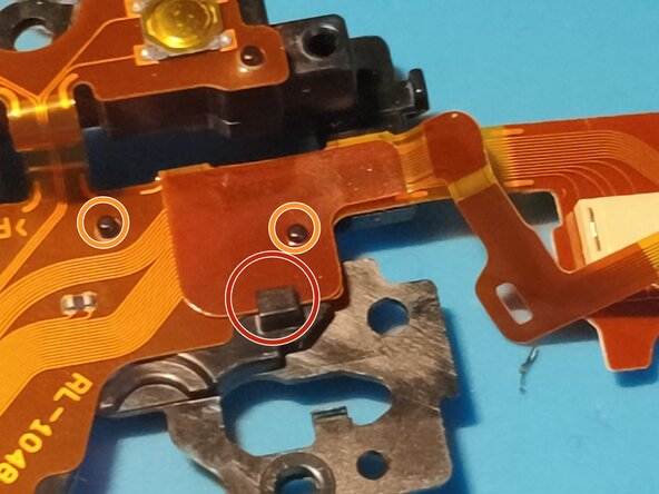
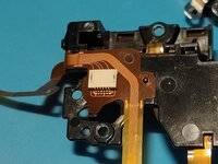
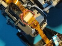
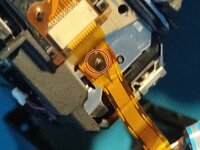
Rotate the camera the way you see the back of the display. Locate the part marked with a rectangle in Picture 1.
-
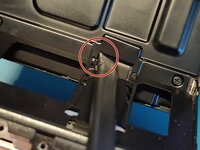
Gently apply pressure to the place marked with a red circle in Picture 2. Make sure not to put pressure on the flex cable itself, that will most likely damage it.
-
Note: During reassembly simply slide it from the opposite side as you pushed. It should click into place via those 2 little tabs on the end.
-
-
-
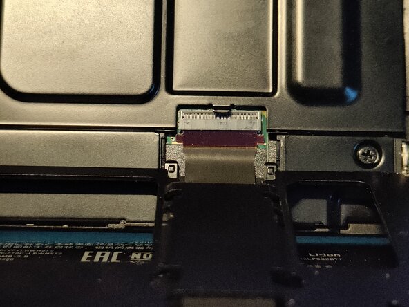
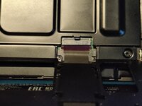
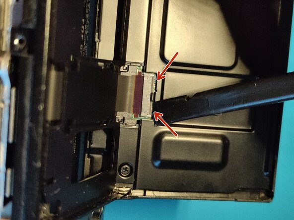
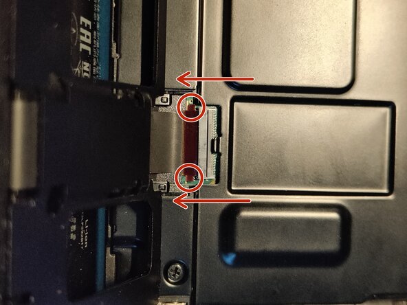
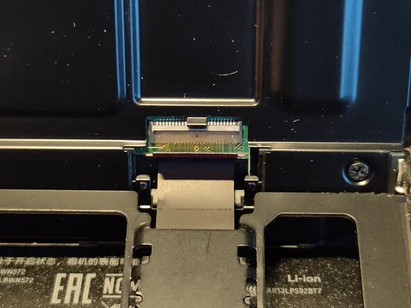
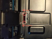
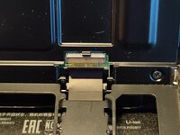
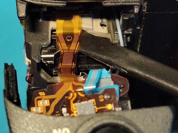
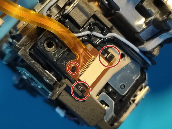
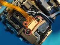
Gently open the FPC connector locking tab on both sides - marked with arrows.
-
Gently push on both marked points in the direction of the arrows.
-
Carefully remove the flex cable.
-
Note: The flex cable is slightly glued to the guide metal on the display frame itself, make sure to remove it gently. - shown in Step 10
-
Tip: Put one or two drops of isopropyl alcohol behind the glue, it should soak into the adhesive and release it much more easily without damaging the flex cable.
-
Once the isopropyl dries, the adhesive should be sticky again.
-
-
-
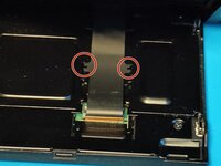
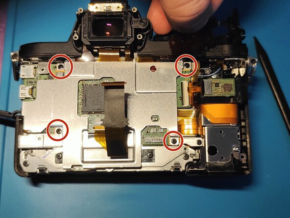
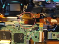
Remove 4 tiny screws marked with red circles on Picture 1 with a P00 screwdriver.
-
Gently remove the display with together with the hinge assembly, make sure to remove the flex cable from the back of the hinge assembly.
-
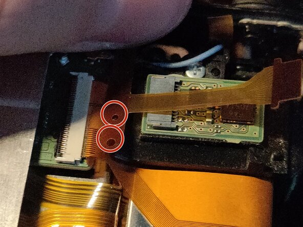
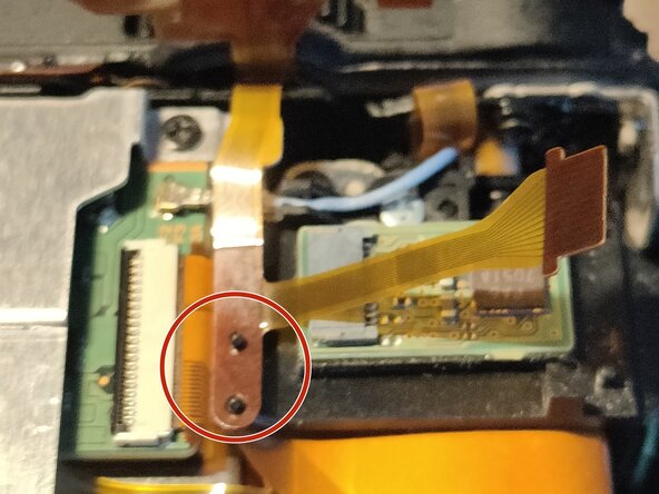
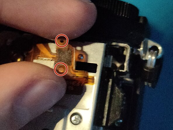
Carefully pull the flex cable away from the hinge. You can help by pushing the cable from the underside. Make sure to disconnect the cable from those 2 points marked with red circles on Picture 2.
-
The cable is slightly glued to the hinge assembly (as mentioned in Step 9)
-
-
-
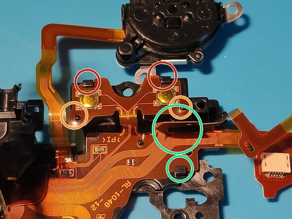
Remove 3 black screws marked with red circles with a P00 screwdriver.
-
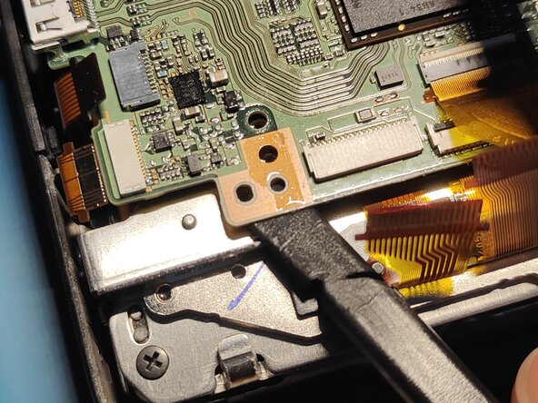
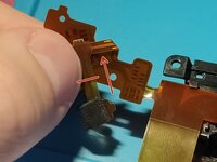
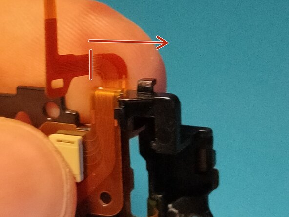
Gently insert your prying tool as shown in Picture 2. (marked with green arrow). Make sure not to insert it past the red line as you might damage the flex cable corresponding to the "MENU" button.
-
Note: You can pry anywhere else e.g. from the bottom side, just make sure not to damage any flex cables.
-
Carefully guide the LCD Flex Cable through the opening and remove the front shell.
-
Note: Ensure that the AF/MF / AEL switch is set to AEL before reinstallation. If you don't, as you switch from AF/MF to AEL afterwards it will first snap past the small trigger and potentially bend the plastic arm or damage the switch.
-
Huge thanks for Adam Macdonald for pointing this out!
-
-
-
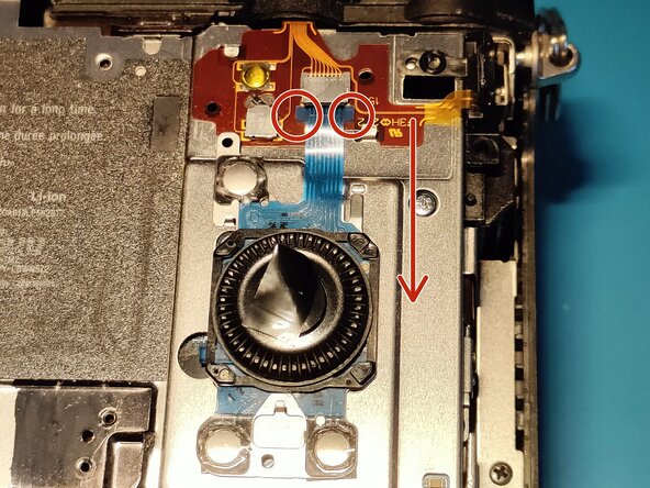
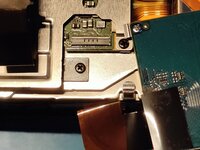
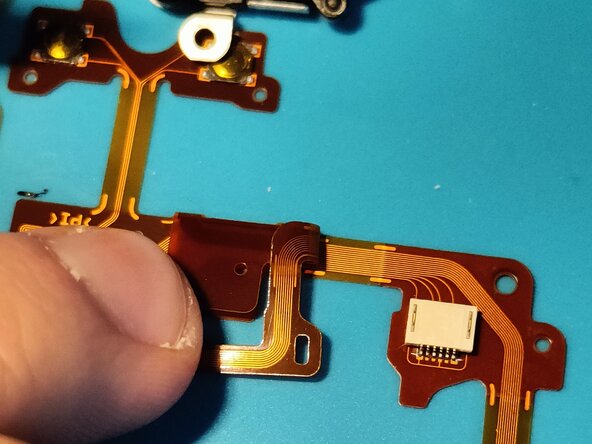
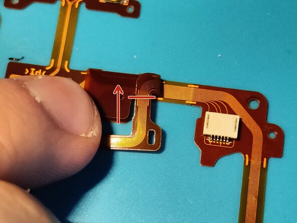
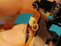
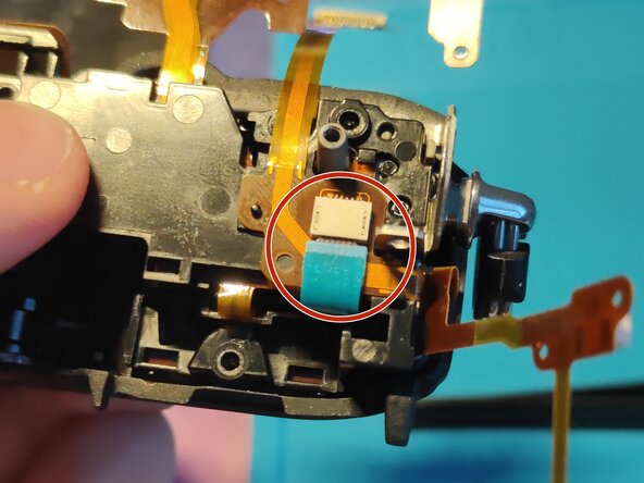
Remove the tape covering the FPC connector marked in Picture 1.
-
Note: I usually just put it on the scroll wheel itself so I don't lose it and it stays sticky as well.
-
Gently pull out the flex cable via the 2 little tabs marked with red circles in Picture 2. Make sure to pull in the direction of the arrow.
-
Voilà! The flex cable is out!
-
-
-
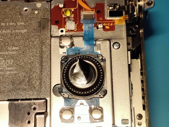
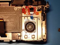
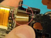
Gently put with a prying tool pressure on the spot marked in Picture 1.
-
Voilà it pops out of place!
-
-
-
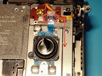
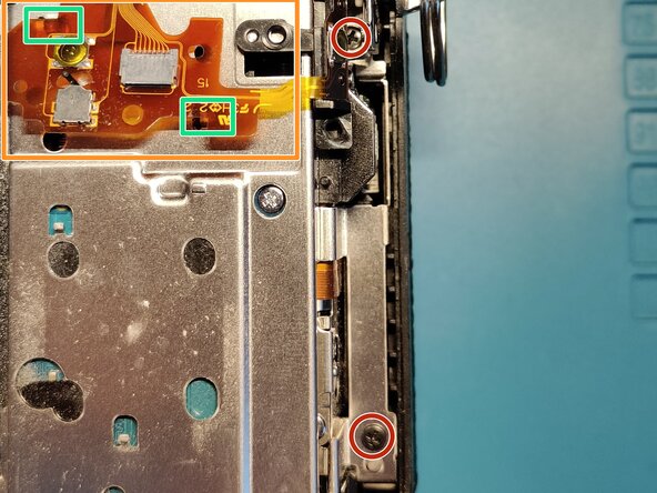
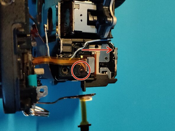
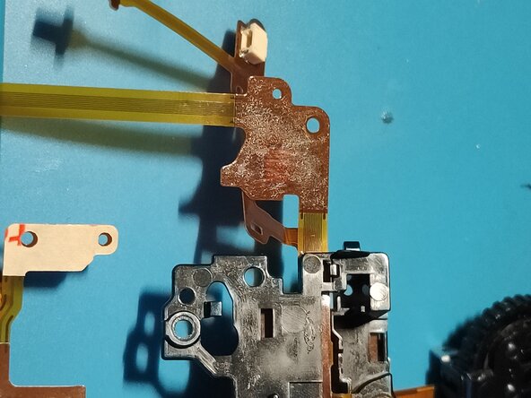
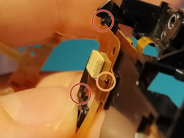
First make slide out the flex cable marked with an orange rectangle out of the metal tabs marked with green rectangles, so you can remove the whole metal bracket later on.
-
Remove the 2 screws marked with red circles on the right side of the camera.
-
Note: Be careful when removing the upper screw, gently pull the ribbon cable aside.
-
Note: Keep track of the screws - easiest is to collect them in order this way you can easily put it back together, you just have to do it in reverse.
-
-
-
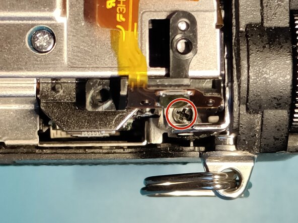
Remove the screws marked with red circles, the second one probably will be a bit harder to remove due to the magnets of the IBIS.
-
You can use a pair of tweezers, or a stronger magnet to get the screw out of the hole.
-
Gently remove the black tape holding the metal bracket in place by prying under the tape with a plastic spudger. Make sure to keep this tape, you'll need it while reassembly.
-
-
-
Gently remove the metal bracket, while paying attention to guide through the LCD flex cable the hole it is meant to go through.
-
Note: The left side of the metal bracket may be a bit harder to remove, take a closer look on the left side and gently wiggle it out.
-
I recommend placing the tape on the metal bracket it self, so you don't lose it for sure.
-
-
-
Remove the one screw holding the SD card reader in place marked with a red circle.
-
Lift up the locking tab on the connector which is on the mainboard.
-
Note: I'd recommend doing this, much easier to while reassembly, if you need to change the SD card reader, obviously you have to remove it from the SD card reader it self - lift the tape and remove it from that side.
-
Note: During reassembly make sure the metal part marked with an orange rectangle in picture 2 goes on top of the metal bracket, not under it.
-
-
-
-
Remove the 4 black screws marked with red circles and gently pry under the metal bracket as shown in Picture 2.
-
-
-
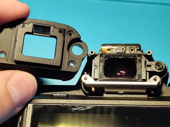
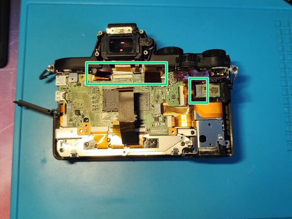
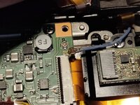
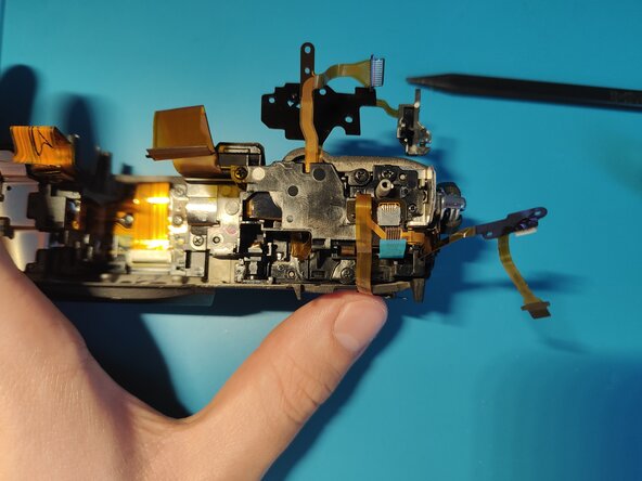
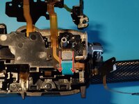
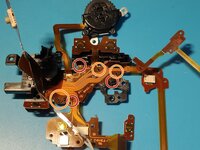
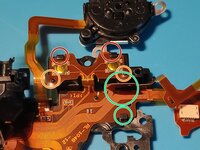
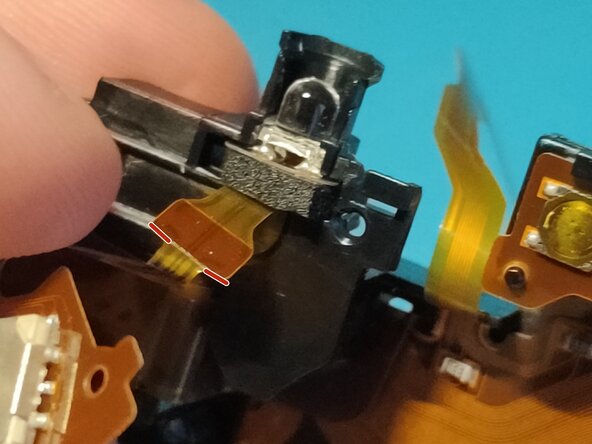
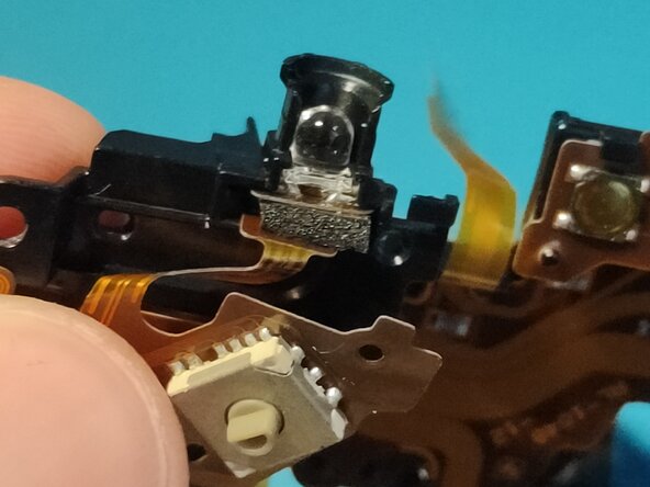
Note: If you are here to replace the top flex cable, you only need to remove the EVF and disconnect the cables marked with green rectangles.
-
This way you reduce the risk of tearing other flex cables on the motherboard (e.g. sensor & ibis flex cable which you can't replace by themselves)
-
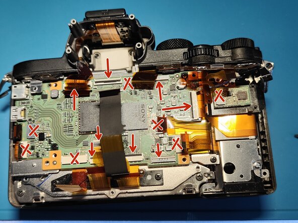
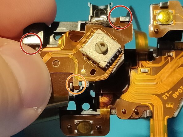
If you are here to disassemble further, lift up the locking tabs on the connectors which have and remove disconnect all of the flex cables while being careful not to tear any of them.
-
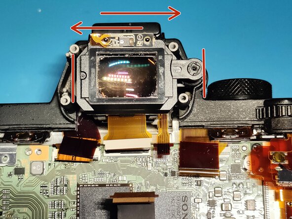
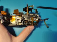
After disconnecting the flex cables you need to, to remove the EVF put your index finger and thumb finger on the two sides marked with two red lines. Hold it firmly and start slowly wiggling left to right, while slightly pulling up on the EVF.
-
Note: You don't need to remove the LCD flex cable from the motherboard, you can leave it there as is - unless you need to replace it obviously.
-
As for the connectors: If a connector doesn't have a locking tab, its marked with an X in picture 3. If a connector does have one, the arrow points at the locking tab itself, you have to open it the same way as the arrow goes.
-
-
-
Note: Just to be sure, if you are here to replace the top flex cable in your camera, please skip to Step 21. There is no need to remove the motherboard in your case.
-
If you are here to remove your motherboard, remove the 2 screws marked with red circles holding it in and remove the Wi-Fi cable from the board, by putting your spudger under it and slightly lifting it.
-
With a spudger lift the mainboard up and carefully remove it from the camera.
-
Make sure not to damage any flex cables while doing so.
-
-
-
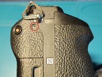
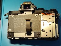
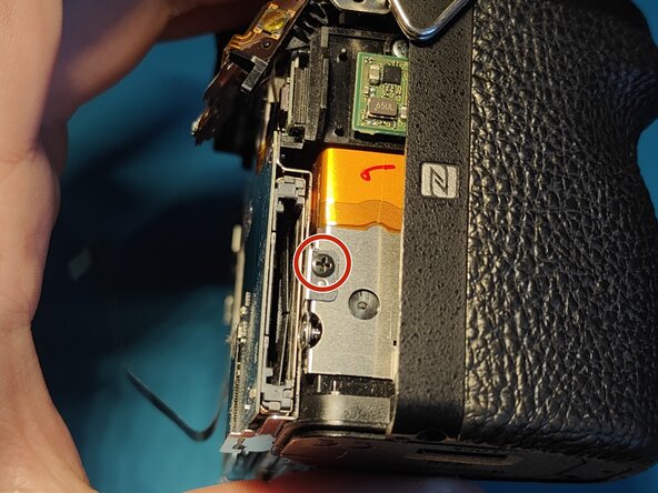
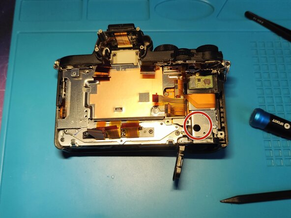
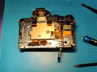
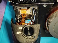
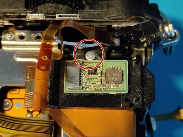
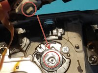
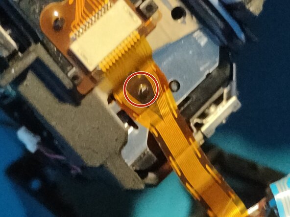
Locate the battery compartment and the large hole on it.
-
Put your screwdriver through it and carefully remove the screw.
-
-
-
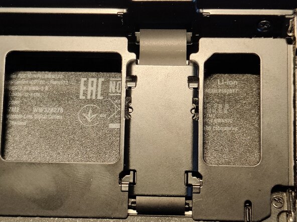
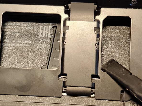
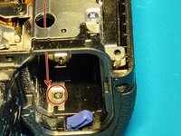
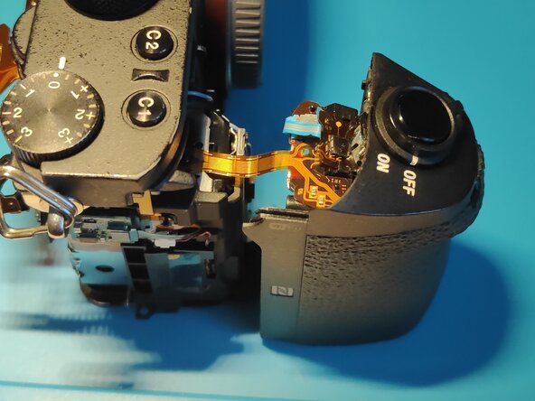
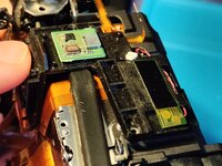
Insert a spudger like shown in picture one and gently pull the grip in the direction of the arrow.
-
Keep in mind not to pull too hard, there is a flex cable connecting the grip to the top assembly, don't risk tearing it.
-
-
-
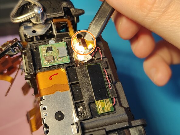
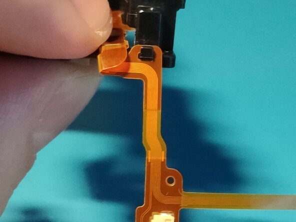
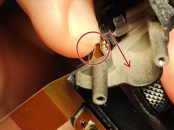
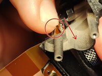
Gently pry under the flex cable where it has a hole in it, and gently remove it from the connector.
-
-
-
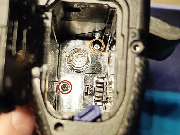
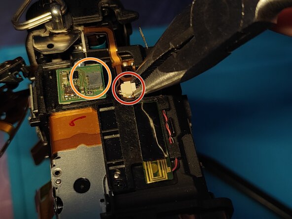
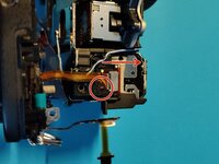
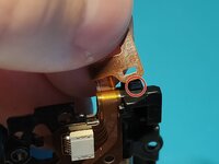
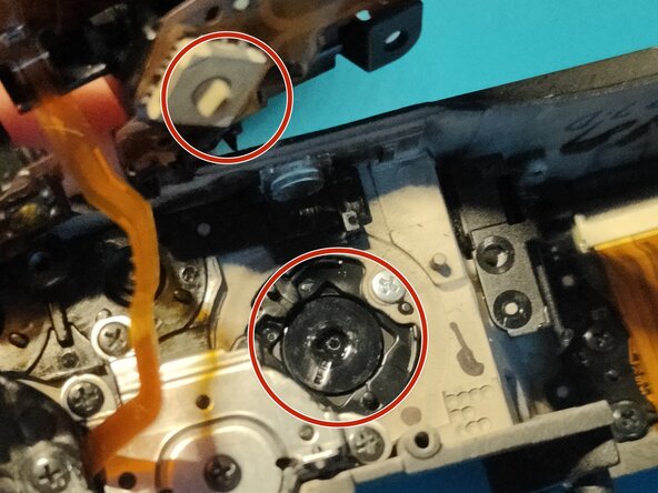
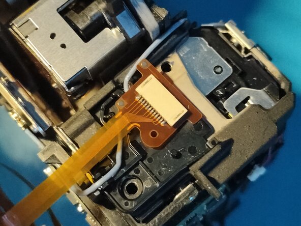
Carefully disconnect the flex cable from the little board marked with an orange circle - it is already disconnected in the picture.
-
Carefully disconnect the cable from the JST connector (marked with a red circle) with a pair of pliers, make sure NOT TO PULL on the connector it self, as it rips easily off the flex cable. Remove it as shown in the picture.
-
Insert a spudger under the flex cable to separate it from the body, it is held down by adhesive.
-
Note: This is part of the top flex cable, if you got a replacement it will most likely come with adhesive on this part.
-
-
-
Note: If you are here to replace the top flex cable, skip to Step 26, as this step is unnecessary to remove the top flex cable.
-
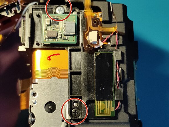
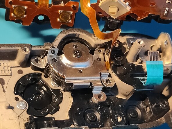
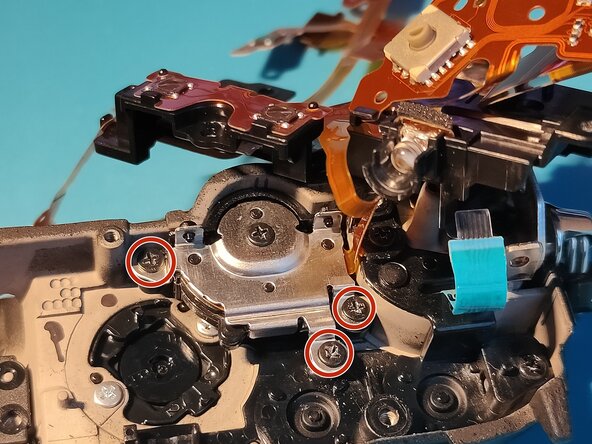
Remove the two silver and one black screws holding the plastic bracket in place. (marked with red circles)
-
Gently pry under the plastic bracket with a spudger and put it aside.
-
-
-
Remove the one screw on the left and two screws located where you removed the EVF from (marked with red circles).
-
Gently pry as shown in Picture 3 and carefully lift the top assembly. There is still a flex cable mounted, which will be removed in the last step.
-
-
-
Gently tilt the top assembly towards the face (where the display is) of the camera and locate the last flex cable that's mounted.
-
Pry up the flex cable - there is a hole in it, that holds it in place, then push it as the arrow shows.
-
Finally, remove the top assembly and wipe off your tear's of joy because of succeeding.
-
To continue the replacement process, please check the follow up guide on my profile.
-
-
-
Finally you can start to replace the Top Flex Cable in your A7 II! Please make sure NOT TO THROW AWAY YOUR OLD FLEX CABLE, YOU WILL NEED TO CHANGE SOME PARTS OVER!
-
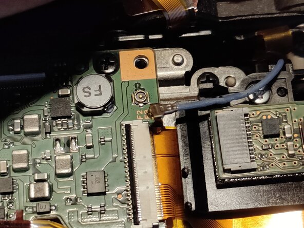
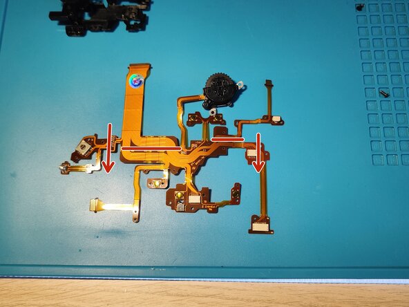
Locate the blue cable and gently remove it from the connector. Push it in the direction of the arrows as shown.
-
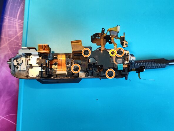
Remove 5 screws in total marked with orange circles in Picture 1. Keep in mind there is a "hidden" screw under one of the flex cables, this one is marked with a yellow circle.
-
I highly recommend getting a FixMat from iFixit, so you can easily put them in the same layout as in the top part, this way you will know for sure which screw goes where.
-
I usually don't do this, just while doing this part cause there aren't many screws.
-
-
-
After removing the screws holding the plastic bracket in place, gently guide through the blue flex cable through the opening and pull the plastic bracket aside.
-
Note: While reassembly, make sure to guide this blue flex cable back through that opening while trying to reinsert the plastic bracket in place.
-
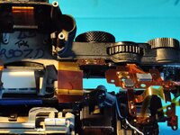
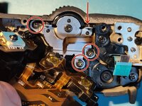
Remove the 3 screws marked with red circles in Picture 1. Keep track of where each screw goes - I can only recommend the same thing I did in Step 1.
-
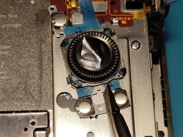
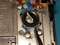
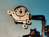
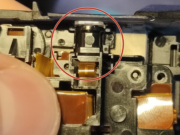
Push on the scroll wheel from the outside as the arrow shows in Picture 1.
-
Remove a single screw holding in a metal bracket covering the scroll wheel in Picture 3, please also take a close look at how it's put together. Keep track of this screw, you'll need it in the next step.
-
-
-
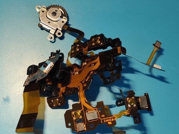
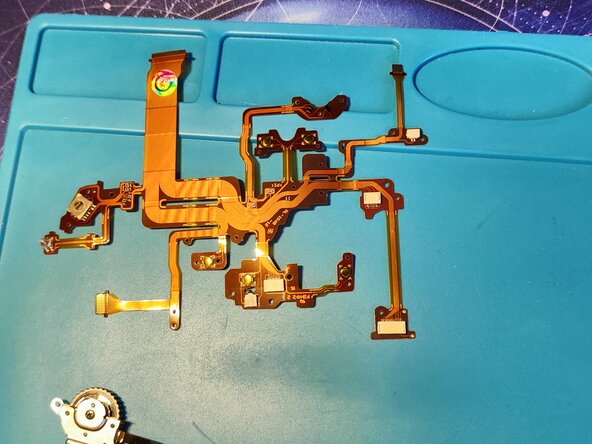
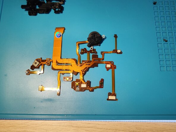
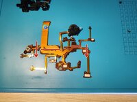
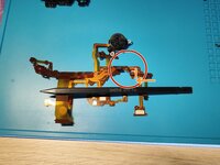
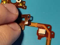
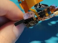
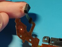
This is what the new flex cable looks like, straight from China. It doesn't look much like the one you just took out of the camera, does it?
-
Well, yes, there's still some work to be done on it.
-
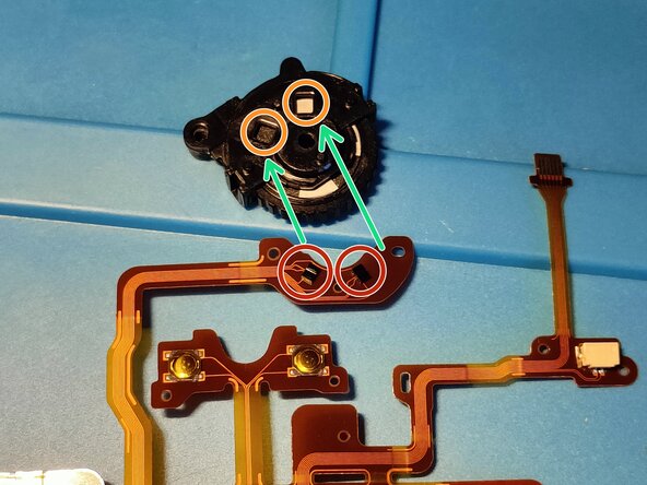
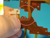
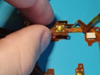
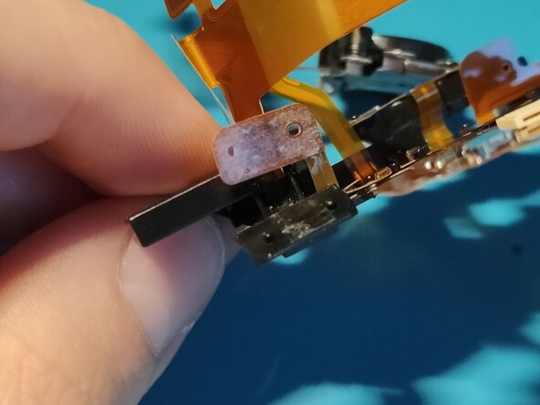
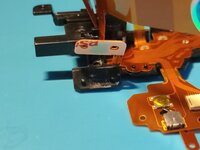
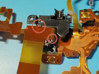
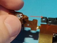
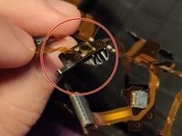
Grab the scroll wheel you previously removed in Step 3, and line up the two black (sensors?) things on the flex cable with the holes on the scroll wheel itself, both marked with circles and arrows in Picture 2.
-
Attach the metal bracket holding the wheel in place with the screw you removed in Step 3. Please put your flex cable in the exact position as you see in Picture 3 then proceed to the next step and follow each step with caution.
-
Origami begins.
-
-
-
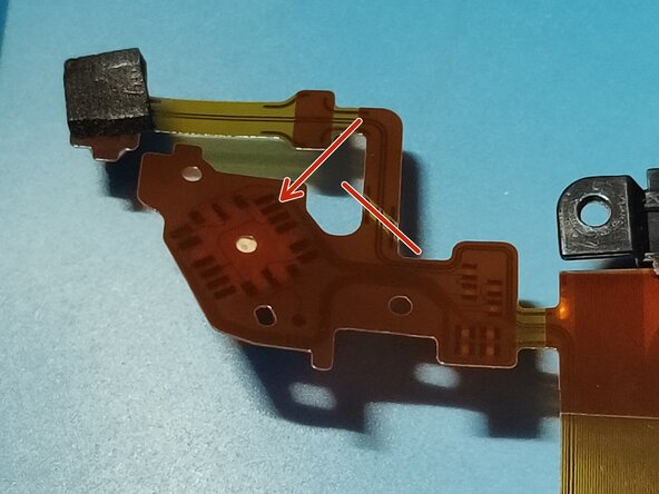
Bend the flex cable along the red lines, in the direction of the red arrows as shown in Picture 1. You should end up like you see in Picture 2.
-
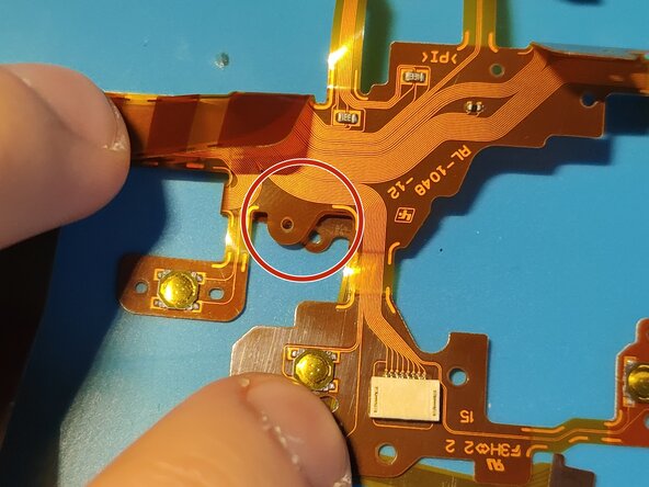
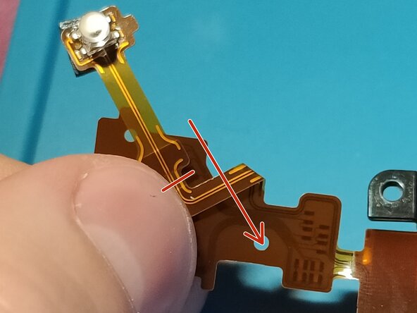
Focus on the part marked with a red circle in Picture 2. Fold that small flex cable along the orange line in the direction of the arrow as shown in Picture 2.
-
Note: In a flex cable, if it is see through, it usually means, that you can fold that part.
-
You should should end up like you see in Picture 3.
-
-
-
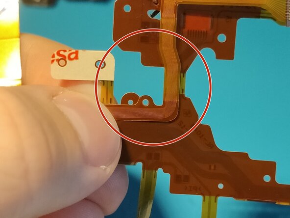
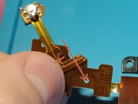
Bend the same small flex cable along the red line in the direction of the arrow as shown in Picture 1.
-
You should should end up like you see in Picture 2.
-
-
-
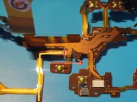
Fold a small part of the flex cable marked with yellow lines along the red line in the direction of the arrow as shown in Picture 1.
-
Make sure to fold it under the flex cable, not over it.
-
You should end up as you see in Picture 2 (front side) and in Picture 3 (back side).
-
-
-
Bend this part of the flex cable at two places, in the direction of the color matching arrows.
-
You don't need to bend it too much, just slightly so it kind of stays in place. It will go into it's place in the plastic bracket anyways, this step is just to make your life a bit easier.
-
-
-
As I asked in the first step, you should keep your old flex cable for 2 reasons: you can check the new one if its in the same way & you need to transfer some parts over.
-
If you haven't already, remove the old flex cable from the plastic bracket and try to fit the new one in. Make sure the large part on the left goes in where it should - marked with a red circle in Picture 1.
-
There are tiny black plastic things that you need to put the flex cable under, you can see these marked with red circles in Picture 2.
-
There are tiny black "spikes" that must line up with some holes on the flex cable itself, these are marked with orange circles in Picture 2.
-
Note: I highly recommend pushing on them after you successfully fitted the new flex cable under the black plastic holders.
-
Make sure that the flex cable is under the plastic holders as you see in Picture 3 for example.
-
-
-
Insert the flex cable under the 2 plastic tabs and push on the ends to push the small "spikes" in the holes of the flex cable.
-
Make sure to put the small part of the flex cable - marked with a green circle - under the plastic tab securing it in place. Also make sure the little spike goes through the hole in the flex cable.
-
Remove the small adhesive from the "Menu" button and push it in place. Make sure the 2 holes line up and push the spikes through the holes.
-
-
-
Guide the flex cable under the plastic tabs marked with red circles as shown in Picture 1.
-
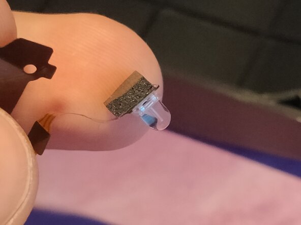
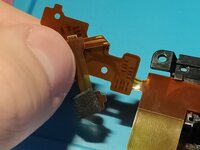
Locate the AF assist light on the old flex cable and gently remove the black sponge from the back and transfer it over to the new one.
-
-
-
Fold the whole flex cable along the red line in the direction of the arrow as you can see it in Picture 1. You should end up as you can see it in Picture 2.
-
Fold the whole flex cable along the red line in the direction of the arrow as you can see it in Picture 2. You should end up as you can see it in Picture 3.
-
Note: The flex cable should be on top of the other cable, not under it.
-
-
-
Fold the whole flex cable along the red line in the direction of the arrow as you can see it in Picture 1. You should end up as you can see it in Picture 2.
-
Fold the whole flex cable over and put the AF assist lamp in place as you can see it in Picture 3 then proceed to the next step.
-
-
-
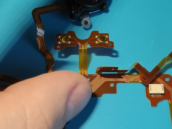
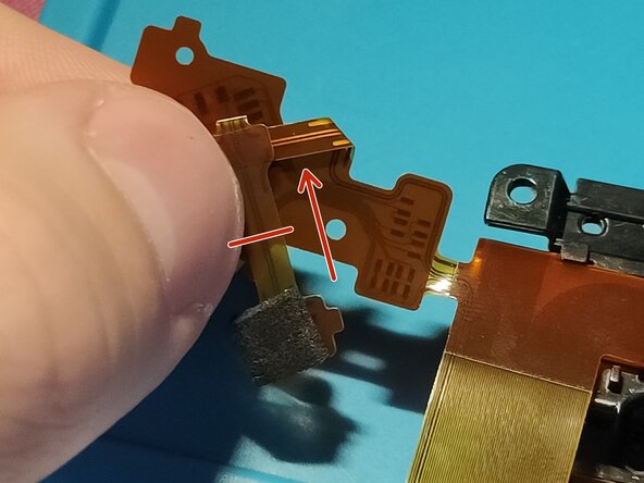
Gently push on the part of the flex cable which is marked with red lines in Picture 1 and try to push it in the hole.
-
The top of the flex cable should be roughly at the top of the black sponge - as you can see it in Picture 2.
-
Gently insert the mode selector part of the flex cable under the plastic tabs marked with red circles in Picture 3. The one marked with an orange circle should be between 2 plastic tabs.
-
-
-
Make sure to check again if you have correctly routed the flex cable under the plastic tab marked with a red circle and successfully put the plastic "spikes" through the holes of the flex cable - marked with orange circles - in Picture 1.
-
Remove the protective film from a part of the flex cable marked with a red circle in Picture 2. This will reveal the adhesive underneath.
-
-
-
After removing the protective film covering the adhesive, firmly push it on to the surface as you can see in Picture 2.
-
Please make sure the plastic "spike" lines up with the guiding hole on the flex cable - marked with an orange circle - and also that its under the plastic tabs - marked with red circles - as you can see in Picture 3.
-
-
-
Fold the flex cable along the red line in the direction of the arrow as you can see it in Picture 1. You should have already done this step once before, therefore it should be easier.
-
Put the hole over the little plastic tab - marked with a red circle in Picture 2 -, you should end up like you see in Picture 3.
-
Note: While reassembly, it might come loose, make sure to pay attention when you put it together that it did not. If it did, try to adjust it. You can slightly lift the whole top assembly as well a bit, fix it then put it back in place.
-
-
-
And you are done with the origami itself, now its time to put it back in the top assembly.
-
First insert the scroll wheel in place and make sure the flex cable sits right - check Picture 1.
-
Put the 3 screws back to hold it in, spots marked with red circles in Picture 2.
-
-
-
Guide the blue flex cable through the hole in the plastic and connect it in place/try to keep it in the hole while you put the flex cable back in place.
-
Make sure that the AF assist lamp is fully in place as you can see in Picture 2.
-
Make sure the wide flex cable you see in Picture 3 goes under the button, not over.
-
-
-
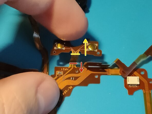
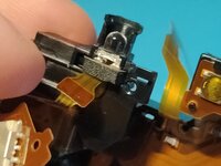
Before inserting the whole new flex cable back in place, check if the Mode Selector wheel is aligned with the switch on the flex cable itself.
-
If it is not, please turn the Mode Selector wheel until it does - see Picture 2 as an example.
-
Gently insert the flex cable in place, if its successfully in place, hold your finger on the plastic part above the Mode Selector wheel.
-
With your other finger put a small amount of pressure on the spot you see marked in Picture 3 towards the arrow.
-
If you have done everything successfully, you should feel it sit nicely in place. Even if it sits in place, I highly recommend testing it before assembling it fully together.
-
Note: Just insert the EVF, the grip and the whole assembly, that is enough to test if it has worked. If it does not work instantly, try taking a picture, then try it again or put some pressure on the right large flex cable.
-
-
-
Lastly put the 5 screws back to hold the plastic piece in place.
-
Tilt the whole top assembly towards you and insert the flex cable you see - around the grip area - in place.
-
It goes under 2 plastic tabs and has a guiding hole as well, as you can see it in Picture 3.
-
-
-
Sorry for the bad quality pictures for this step, I only realized this while making the guide.
-
Insert the flex cable from the grip in the connector you see marked with a red circle in Picture 1.
-
After successfully reconnecting it, use the guide hole on the grip's flex cable and push down on it, this way it stays in place.
-
Finally you can start inserting the whole assembly back in place. Insert the flex cable you see marked with a red circle in Picture 3. Make sure to give it such a bend as you see. (Just like the one it had when you disassembled it)
-
Note: You have to pay attention to a ton of things while doing this step so take it slowly. What exactly you have to pay attention to?
-
Flex cable on the right (the one you had to hook into a plastic tab - Step 16).
-
Wide flex cable goes under the button, not over it - Step 18
-
And lastly, don't tear the grip's flex cable.
-
-
-
If everything works then you have done the job successfully! Start doing the A7 II disassembly guide in reverse and also please check this and the next step out, they are still important.
-
Make sure to use the guide holes and push on the flex cable as you see in Picture 1 -> 2.
-
-
-
Lastly, remove the small plastic piece from the old broken flex cable and transfer it over to the new one.
-
This plastic piece hold the record button in place.
-
Remove the protective film from the new flex cable, and using the guide holes firmly attach it in place.
-
Continue with assembling the camera together, I really hope the guide made the repair job a bit easier. Congratulations if you have got this far!
-


To reassemble your device, follow these instructions in reverse order.
To reassemble your device, follow these instructions in reverse order.
crwdns2935221:0crwdne2935221:0
crwdns2935229:03crwdne2935229:0
crwdns2947412:07crwdne2947412:0
This is an amazing guide! Im waiting for the spare part to arrive. My question is, there is any way of preventing future breaks? Like reinforcing or having something in consideration while changing the part. Thank you for your contribution to the A7II community!
Thanks for your reply, it feels great to receive such a response! Good luck with replacing the flex cable, hopefully it all goes well. I don't really know about any way of reinforcing the flex cable, I don't actually know what breaks in the flex cable itself, I'll probably try and investigate it once.
My pleasure, A7/S/R II-s shouldn't be thrown out just because something breaks, they are still great cameras to use:)
You'll notice on the original OEM cable that some of the bends are at almost full 180 degree angles. It is crazy to me that Sony thought that bending very thin copper wires almost entirely in half was a good idea, especially considering the heat-cycling the camera would go through in its lifetime. There isn't really much you can do about it unfortunately...
Update! The spare part arrived. I followed this guide exactly as described, and my A7II is back in perfect working condition! I can't express how grateful I am for this tutorial, thank you so much!"
The only thing that isn't working is the program dial: for some reason, Panorama and Video modes aren't recognized, so it's as if the dial doesn't change. Despite that, everything else works perfectly (A,S,M and the rest)
As a side note: it would be very useful to know which way the flexible ribbon connectors on the motherboard open, because for someone without knowledge, it can be quite a stressful moment. Once again, thank you!
Hey, thanks for the follow up! I'm glad it partially works now, no idea to be honest why the Panorama & Video modes don't work, but the others do.
As for the side note, thank you! I'll update the guide according to this.