crwdns2915892:0crwdne2915892:0
Warning: The flash capacitors located under the front grip contain dangerous amounts of stored charge and will need to be safely discharged before removing the motherboard. Use a Capacitor Discharging Tool to do so.
The motherboard is crucial for the function of both the software and hardware of the Sony a6500 camera; its failure will result in an inoperable device. If your camera is failing to turn on despite having a functional battery, the motherboard may need replacing. This guide will walk you through the replacement of the motherboard; it requires more steps than the other guides because it is embedded deep inside the camera. This guide will require opening tools, spudger, tweezers, JIS 0 screwdriver, JIS 00 screwdriver, and JIS 000 screwdriver.
crwdns2942213:0crwdne2942213:0
-
-
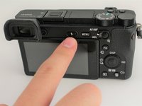
Verify the camera is powered off by setting the switch to OFF.
-
-
-
Flip the camera upside down.
-
Slide the battery compartment lock to OPEN to unlock it.
-
-
-
Push the blue lever aside to release the battery.
-
-
-
Remove the released battery from the compartment.
-
-
-
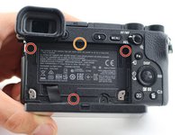
Remove four 3 mm JIS 000 screws.
-
Remove one 3 mm JIS 00 screw.
-
-
-
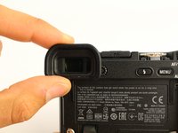
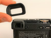
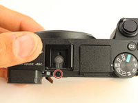
Grasp the viewfinder eyecup; slide it up and off the viewfinder.
-
-
-
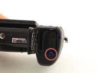
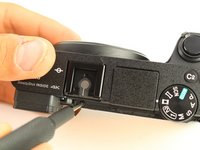
Press the flash popup button on the back of the camera.
-
Remove one 5 mm JIS 00 screw from inside the flash compartment.
-
Remove one 4 mm JIS 00 screw.
-
-
-
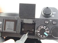
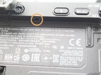
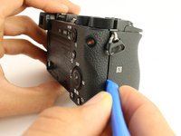
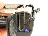
Remove the 2.5 mm JIS 00 screw from the side of the camera near the viewfinder.
-
Use the opening tool to pry off the small cover.
-
Remove two 2.5 mm JIS 00 screws from underneath the cover.
-
Remove a 5 mm JIS 00 screw from underneath the cover.
-
-
-
Remove three 2.5 mm JIS 0 screws from the back face of the camera.
-
Remove one 4 mm JIS 00 screw from the underside of the lip that overhangs the back of the camera.
-
-
-
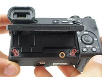
Remove four 4 mm JIS 0 screws from the bottom of the camera.
-
-
-
-
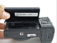
Flip the battery lock switch to open and open the battery compartment.
-
Remove three 2.5 mm JIS 00 screws from the top of the battery compartment.
These 3 screws were 4mm on my camera. Mine may have been disassembled previously.
-
-
-
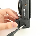
Use the plastic opening tool to begin prying off the back of the camera from the side.
-
Continue to loosen the back until you can open it from the bottom.
-
-
crwdns2935267:0crwdne2935267:0Tweezers$4.99
-
Open the back of the camera.
-
Use tweezers to remove two ribbon connectors from underneath the back. One connects to the LCD display and the other connects to the right side behind the battery compartment.
-
-
-
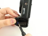
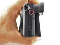
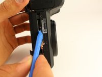
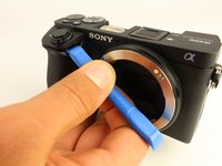
Use the plastic opening tool to peel down the rubber grip around the handle at least 1 cm.
-
Remove one 3 mm JIS 000 screw from underneath the rubber grip on the right side.
-
Remove one 4 mm JIS 000 screw from the left side.
Left side contained a 3mm screw as well on my camera. Mine may have been disassembled previously though.
-
-
-
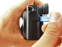
Remove one 2.5 mm JIS 00 screw from the top next to the flash mount.
-
-
-
Insert a long, thin JIS 00 screwdriver through the two holes and into the battery compartment; remove the two 5mm JIS 00 screws inside it.
-
-
-
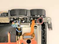
Use the long, thin, screwdriver to remove one 5 mm JIS 00 screw inside the camera accessible below the dials from the back.
is there a simple way to remove that knob what is switching between programs (Manual, Shutter Priority, Aperture Priority)
My camera, during video recording is swithing by herself between programs and at the same time stopping video recording, and I’m thinking that maybe it needs a bit of contact cleaning
-
-
-
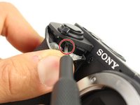
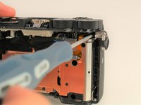
Use the plastic opening tool to gently lift up the shutter button assembly.
-
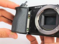
Grasp the front grip from the top and bottom and pull it off. It should come off easily with the shutter button out of the way.
Can you do a teardown of the top from a sony a6400? Because this from part with the shutter button is not separate as in a6500, in the a6400 is part of the top as a one piece and I havent found any dissassembly process for the a6400.
-
-
-
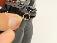
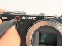
Remove one 2.5 mm JIS 00 screw from where the shutter button assembly used to be.
-
Remove one 3 mm JIS 00 screw from the side of the camera.
-
-
-
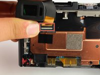
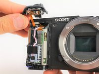
Carefully unplug the two ribbon connectors attaching the top assembly to the rest of the camera.
How can I plug the flash ribbon connector back in when reassembling the camera? I successfully replaced the flash, following your guide, but now I am stuck as I can't figure out how to plug that connector in. The plug appears to be hidden.
-
-
-
From the top of the camera remove one 4mm JIS 00 screw.
-
Remove one 5mm JIS 00 screw and the plastic bushing around it.
-
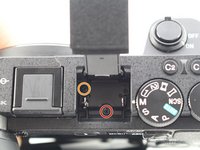
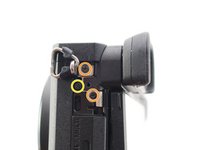
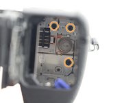
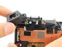
Remove the viewfinder's protective cover.
-
-
-
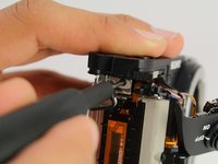
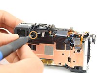
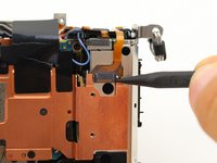
Use the spudger to pry the light sensor off the side of the viewfinder.
-
Remove one 2.5mm JIS 000 screw on the side of the viewfinder to release it.
-
-
-
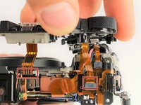
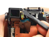
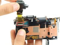
Lift the viewfinder out and flip up the tab to release the wire ribbon where it is connected to the motherboard.
-
-
-
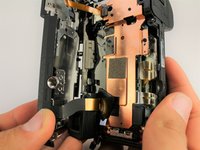
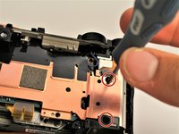
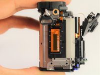
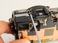
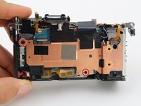
Remove two 2.5mm JIS 00 screws from the left side and bottom of the copper shielding.
-
Remove two 2mm JIS 000 screws from the right side of the copper shielding.
-
Pull the entire copper shielding piece off.
-
-
-
Remove one 4mm JIS 00 screw holding down a plastic spacer on the bottom left of the motherboard.
-
-
crwdns2935267:0crwdne2935267:0Tweezers$4.99
-
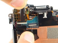
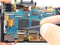
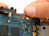
Use tweezers to carefully pull out the first wire ribbon on the left side of the motherboard.
-
Use the spudger to flip up the tab locking in the wire ribbons at the bottom of the motherboard, then pull them out with tweezers.
-
-
-
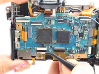
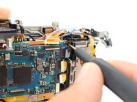
Carefully use tweezers to remove four wire ribbons on the right side of the motherboard.
-
Remove the last two wire ribbons on the top of the motherboard by flipping up the locking tab and pulling them out.
-
Pull the blue coaxial cable up off the board.
-
-
-
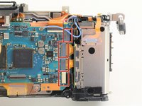
Remove one 4mm JIS 00 screw from the upper right of the motherboard and another from the far left.
-
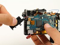
Remove the plastic housing for the power and HDMI ports.
-
-
-
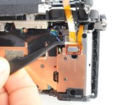
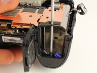
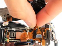
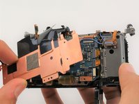
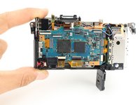
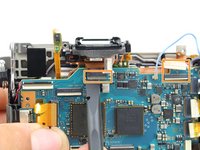
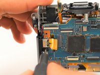
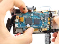
Grasp the motherboard from the sides and lift it up. It is still connected by two wires on the bottom right side.
-
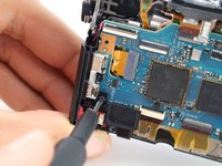
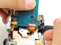
Pull the wire ribbon on the underside off with tweezers.
-
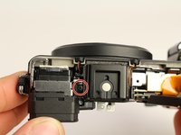
After you have discharged the capacitor, pull the yellow wire harness out using tweezers.
-
-
-
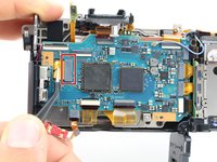
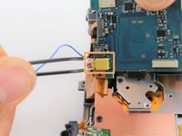
Disconnect the wire ribbon connecting the power port to the board.
-


To reassemble your device, follow these instructions in reverse order.
To reassemble your device, follow these instructions in reverse order.
crwdns2935221:0crwdne2935221:0
crwdns2935229:06crwdne2935229:0

crwdns2915084:0crwdne2915084:0

Cal Poly, Team S11-G5, Regan Fall 2019 crwdns2935289:0Cal Poly, Team S11-G5, Regan Fall 2019crwdne2935289:0
CPSU-REGAN-F19S11G5
crwdns2931471:05crwdne2931471:0
crwdns2935297:014crwdne2935297:0