crwdns2915892:0crwdne2915892:0
A motherboard is a printed circuit board containing the principal components of a computer or other device, with connectors into which other circuit boards can be slotted. If a short circuit happens, your camera might not be able to turn on. This guide will guide you step by step on how to replace the motherboard of your Sony α6000 camera.
Before you begin the repair, make sure to turn off your camera, disconnect it from any power source, and remove the battery.
Be cautious while working on the camera—some internal components, like capacitors, can hold a charge and may shock you or damage the camera's internal circuits. Use a capacitor discharge tool to safely release any stored energy before proceeding. For more information about capacitors, check out the Capacitors 101 Wiki. You can also follow this guide to make your own capacitor discharge tool.
crwdns2942213:0crwdne2942213:0
-
-
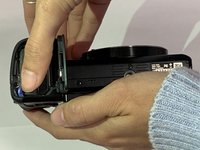
Begin by placing the camera facing upside down.
-
-
-
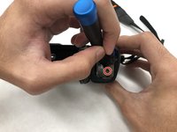
Slide the notched locking bar on the battery compartment from LOCK to OPEN.
-
-
-
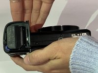
Push the small blue bar horizontally off of the battery.
-
-
-
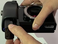
Remove the 1.75mm Phillips #00 screw from the left side of the camera.
-
-
-
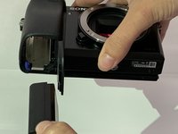
Remove the two 1.75mm Phillips #00 screws from inside the battery department.
-
-
-
Remove the 1.75mm screw using a Phillips #00 head from underneath the flash.
-
-
crwdns2935267:0crwdne2935267:0Tweezers$4.99
-
Carefully remove the ribbon of the flash from the socket by using a pair of tweezers.
-
-
-
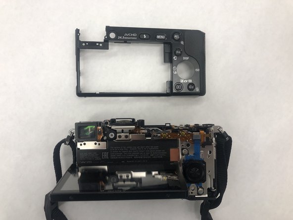
The top of the camera will be free and can be removed.
-
Set the top of the camera to the side.
-
-
-
-
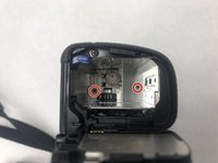
Remove the three 1.75mm Phillips #00 screws just below the eye sensor.
-
-
-
Remove the 1.75mm Phillips #00 screw from underneath the SD card cover.
-
-
-
Remove two 1.75mm Phillips #00 screws from the bottom of the camera.
-
-
-
Remove the 1.25mm screw from the right side underneath the battery cover.
-
-
-
Remove the 1.75mm Phillips #00 screw just to the right of the eye sensor.
-
-
-
Remove the back panel of the camera.
-
-
-
Remove the two 1.25mm Phillips #00 screws near the top of the camera, just to the left of the eye socket.
-
-
-
Remove the two 1.75mm Phillips #00 screws from the bottom of the camera.
-
-
-
Remove the three 1.75mm Phillips #00 screws from the right side of the camera.
-
-
-
Remove one ribbon that is attached to the selector wheel with a pair of tweezers.
-
-
-
lift up the protector plate and remove one ribbon that is attached to the LCD screen with a pair of tweezers.
-
-
-
Detach the LCD screen from the back portion of the camera and set it aside.
-
-
-
Lift up the black cover to reveal the motherboard and ten ribbons.
-
Use a pair of tweezers to gently pull the ribbon cables out of their sockets on the motherboard.
-
-
-
Remove the four 1.25mm Phillips #00 screws located on the borders of the motherboard.
-
-
-
Remove the power supply at the bottom right hand corner with a pair of tweezers.
-
-
-
Lift the motherboard up and remove the last ribbon cable with a pair of tweezers.
-
-
-
Remove the motherboard and set aside.
-


To reassemble your device, follow these instructions in reverse order.
To reassemble your device, follow these instructions in reverse order.
crwdns2935221:0crwdne2935221:0
crwdns2935229:03crwdne2935229:0
crwdns2915084:0crwdne2915084:0

IUPUI, Team S2-G2, Harley Summer 2019 crwdns2935289:0IUPUI, Team S2-G2, Harley Summer 2019crwdne2935289:0
IUPUI-HARLEY-SU19S2G2
crwdns2931471:03crwdne2931471:0
crwdns2935297:07crwdne2935297:0
crwdns2947412:05crwdne2947412:0
I have been wondering what path I will take when I replace my battery contacts part and this looks like an ideal guide for how I can do it. I wondered why you don’t discharge the capacitor before removing ribbon cables. When I removed the top block off my nex-6 I did discharge the capacitor as what the service manual suggested before I removed the control dial and flash ribbon cables. Before I did it I found a youtube about using wires to the discharge contacts going to a light bulb to safely discharge the capacitor. The service manual suggests using a short jig R:1 k Ω/1 W but since I don’t have access to an electronics store nearby the youtube did the trick trouble free.
I was successful with the dissembling the camera and will need to invest in a working logic board and maybe something that is part of the shutter. I was hoping the camera would be an easy fix but sometimes this isn’t this case.
is there a way to fix the hdmi out port without buying a new mother board?
Hi this is a really helpful guide thank you but I need to go a bit further to replace the sticky shutter. Do you have a guide for that please
It really should be mentioned in step 9 to discharge the flash's capacitor using a resistor. It can be sitting at 200+ volts for long after the camera has been turned off, which is quite dangerous.