crwdns2915892:0crwdne2915892:0
There are two boards for the device, a green top level and a blue lower level. This guide will show the steps to replace the top motherboard.
crwdns2942213:0crwdne2942213:0
-
-
Start by using a spudger or plastic opening tool to remove the bottom cover.
-
Once enough of the glue is removed, peel the cover off by hand,
-
-
-
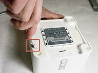
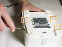
Remove the four 7.5mm length Philips head screws under the rubber cover.
-
-
-
Use a nylon spudger to unsnap the bottom from the sides.
-
Pry until the remaining three points are unsnapped.
-
Once unsnapped, lift the cover.
-
-
-
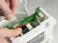
Remove the connection for the front buttons to fully remove the cover.
-
-
-
-
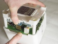
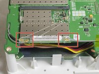
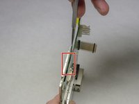
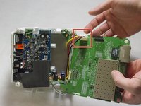
Use a plastic opening tool or spudger to remove the adhesive covering the the WIFI connectors.
-
Gently pull the wires at the connection point to disconnect them from the motherboard.
-
-
-
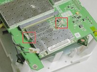
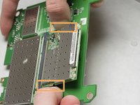
Remove the two pieces of glue holding the WIFI card in place.
-
-
-
Scrape the glued pad underneath the WIFI card to seperate the card from the board.
-
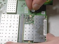
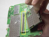
Push apart the two clips holding the WIFI card in the connection.
-
Pull the WIFI card out of the connection.
-
-
-
Remove the 7mm length Phillips screw holding the board in place.
-
-
-
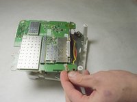
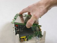
Flip the board over to access the Molex Cable.
-
-
-
Disconnect the Molex Cable from the top motherboard.
-


To reassemble your device, follow these instructions in reverse order.
crwdns2935221:0crwdne2935221:0
crwdns2935229:02crwdne2935229:0
crwdns2935287:0crwdne2935287:0

IUPUI, Team 3-2, Baechle Spring 2016 crwdns2935289:0IUPUI, Team 3-2, Baechle Spring 2016crwdne2935289:0
IUPUI-BAECHLE-S16S3G2
crwdns2931471:04crwdne2931471:0
crwdns2935297:04crwdne2935297:0