crwdns2915892:0crwdne2915892:0
There are two boards for the device, a green top level and a blue lower level. This guide will show the steps to replace the bottom motherboard.
Metal spudgers and similar pry tools can puncture an unprotected battery, potentially causing a fire. When working with electronics, it's important to choose a tool that's ESD-safe to avoid accidental damage to the device. The metal spudger is great when you need serious prying power, but the regular black nylon spudger or a plastic opening tool should be used whenever possible.
crwdns2942213:0crwdne2942213:0
-
-
Start by using a spudger or plastic opening tool to remove the bottom cover.
-
Once enough of the glue is removed, peel the cover off by hand,
-
-
-
Remove the four 7.5mm length Philips head screws under the rubber cover.
-
-
-
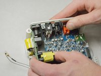
Use a nylon spudger to unsnap the bottom from the sides.
-
Pry until the remaining three points are unsnapped.
-
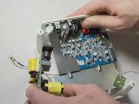
Once unsnapped, lift the cover.
-
-
-
Remove the connection for the front buttons to fully remove the cover.
-
-
-
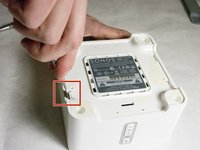
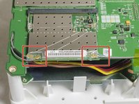
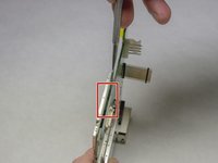
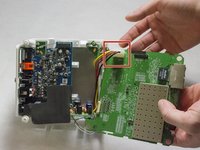
Use a plastic opening tool or spudger to remove the adhesive covering the the WIFI connectors.
-
Gently pull the wires at the connection point to disconnect them from the motherboard.
-
-
-
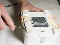
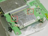
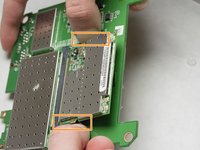
Remove the two pieces of glue holding the WIFI card in place.
-
-
-
-
Scrape the glued pad underneath the WIFI card to seperate the card from the board.
-
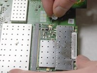
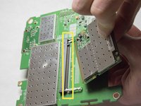
Push apart the two clips holding the WIFI card in the connection.
-
Pull the WIFI card out of the connection.
-
-
-
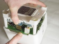
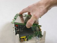
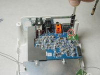
Remove the 7mm length Phillips screw holding the board in place.
-
-
-
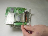
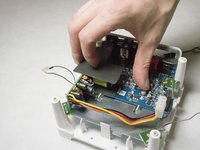
Flip the board over to access the Molex Cable.
-
-
-
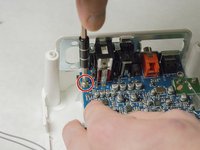
Disconnect the Molex Cable from the top motherboard.
-
-
-
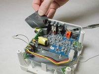
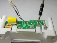
Remove foam protective insulator from the bottom board.
-
-
-
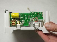
Picture shows the side of the device.
-
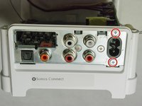
Remove the 7mm length Phillips screw from the power supply motherboard.
-
-
-
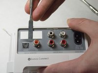
Remove the adhesive backed rear label by using a spudger.
-
Remove the two 8mm length screws as shown.
-
-
-
Pull the power supply out of the back of the device.
Were to order a power suply from the Sonos connect??
rickjonkman @ Hotmail.com
thnx!!
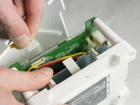
Does anyone please know what the 4 coloured power wires in the Molex are, in terms of 12v, A rating and + or - ? Many thanks.
values are printed on the PCB: -
Red: 3.3v+
Black 3.3v GND
Yellow 14.8v+
Brown 14.8v GND
Andy -
-
-
-
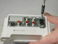
Remove the two 7.5mm length screws on the top of the board.
-
-
-
Remove the other two 8mm length screws on the back of the device. You might have already removed the screws for the power supply, and that's OK!
-
-
-
Slide the board out from the plastic casing.
-


To reassemble your device, follow these instructions in reverse order.
To reassemble your device, follow these instructions in reverse order.
crwdns2935221:0crwdne2935221:0
crwdns2935229:08crwdne2935229:0
crwdns2915084:0crwdne2915084:0

IUPUI, Team 3-2, Baechle Spring 2016 crwdns2935289:0IUPUI, Team 3-2, Baechle Spring 2016crwdne2935289:0
IUPUI-BAECHLE-S16S3G2
crwdns2931471:04crwdne2931471:0
crwdns2935297:04crwdne2935297:0
crwdns2947410:01crwdne2947410:0
I have bad audio on one channel, who supplies parts for this equipment?
Careful as the rubber bottom rips extremely easily. Be very patient.
marcos_peixoto1 - crwdns2934203:0crwdne2934203:0