crwdns2915892:0crwdne2915892:0
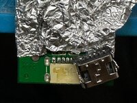
The main problem with the device was a damaged USB socket, which later led to complete device failure (the battery and circuit failed in sequence). This device was brought to me by a friend who couldn’t even open it.
crwdns2942213:0crwdne2942213:0
-
-
The author does not endorse smoking; it may harm your health. This repair is considered only from a circuit-engineering point of view. The repaired device can later be used for other purposes, such as battery or component testing.
-
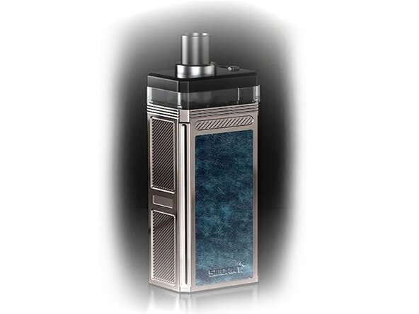
The preamble photo was taken from the official Smoant Pasito 2 promotional website.
-
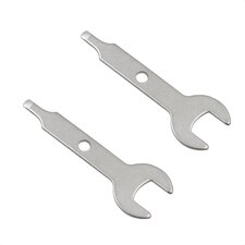
To perform this repair you’ll need: a screwdriver kit, pliers, a 0–15 V lab power supply, and an SMD rework soldering station with a fan. Your skills must include working with lab supply and basic SMD component soldering skills using heat fan.
-
The main problem with the device was a damaged USB socket, which later led to complete device failure (battery and circuit failed in sequence). This device was brought to me by a friend who couldn’t even open it.
-
-
-
To open the device, first pull out the liquid cartridge as shown in the device instructions.
-
Next remove the side labels (stickers) and unscrew the four small screws (two on each side) that hold the frame.
-
Then pull the main frame of the device out of the metal case. This step can be challenging. On my device, because of the swollen battery, I spent nearly an hour to slide it out and completely damaged the plastic with my pliers.
-
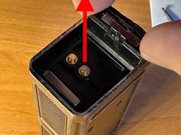
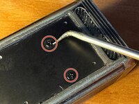
You can help yourself by applying force to the side screw holes through the metal openings. Do this only from the reinforced plastic side. Do not try to pull the frame from the bottom holes or the USB socket—it may cause an explosion because the battery is un-cased and located above those holes (see the photo).
-
-
-
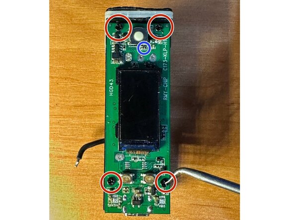
Remove the four small screws attaching the board to the frame.
-
Next, desolder the wires leading to the battery and vaporizer socket. (Your soldering iron power should be 60 W or higher; the board has many copper layers and is difficult to heat.) Be careful not to damage the screen and buttons during initial desoldering.
-
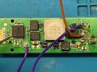
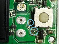
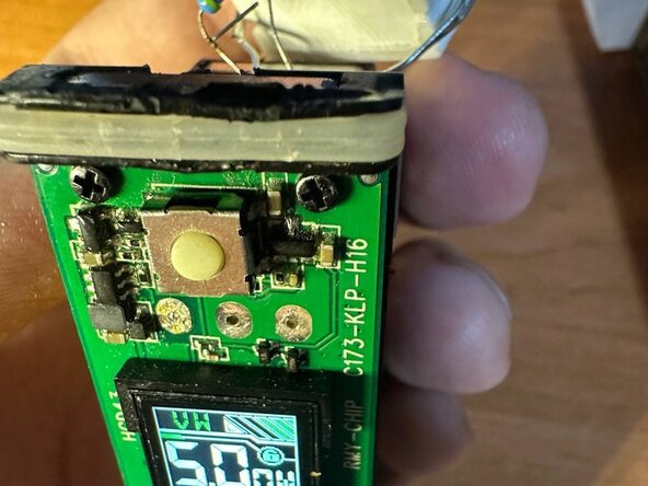
I later desoldered the torn USB socket using an SMD soldering fan. My friend, when trying to pull the frame off, also tore out a small resistor, which I marked with a blue circle. I soldered it back, but it later caused additional trouble, see step 5.
-
-
-
-
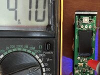
When I applied 3.7 V from a lab supply for circuit testing, it showed me that the input VBAT line was completely shorted.
-
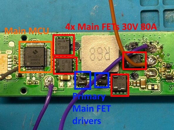
Assuming that the microcontroller rarely fails when powered by a battery (because voltages are not too high), I used my finger to examine the heating components. Two little DFN8 packages (with ELA... mark) were hot.
-
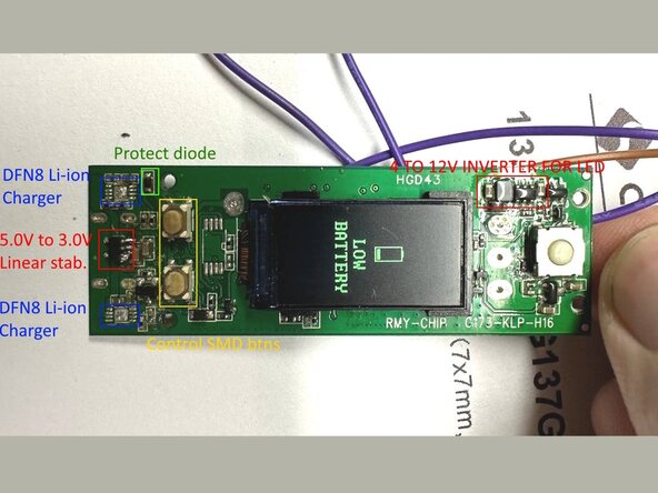
I reverse-engineered these packages and concluded they were small charge controllers (similar to TP4056, etc.) installed in parallel. They were directly connected only to VCC (USB input), VBAT, and GND, without any connection or sending data to the main MCU.
-
So the circuit might start with those packages removed. I carefully desoldered them with a hot-air fan. I recommend removing the entire surrounding compound first, because some side components can be torn away from board with the main package.
-
It took me nearly two hours to find and remove all broken charge components.
-
-
-
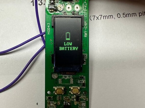
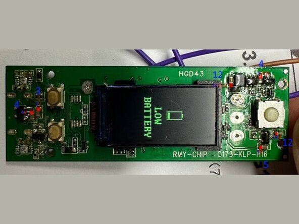
After desoldering the chargers, the schematic tried to boot but showed a “Low Battery” error and then shut down. Debugging this problem was tricky and took four hours of reverse engineering.
-
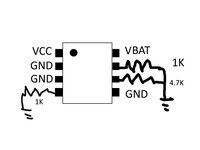
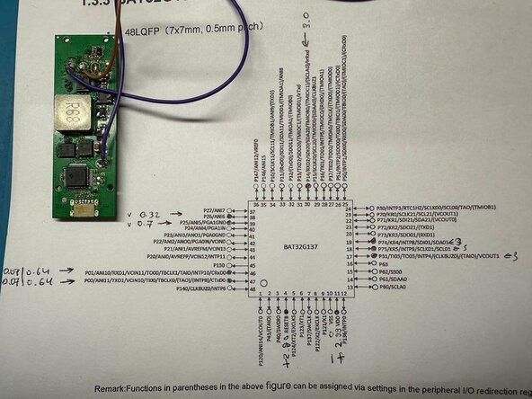
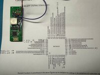
At first I assumed the input voltage must be measured by the CPU - either internally or through an external ADC. I printed the MCU datasheet page (provided in the article attachments) and marked possible ADC inputs.
-
Power measurements showed the main CPU core was powered from 3.0 V via a 3.0 V linear SOT-23 stabilizer located between the removed charger packages. After those measurements the circuit refused to start at all. It turned out that the compound had lifted the SOT-23 package during my previous soldering. Reflowing this IC fixed the power error.
-
But the low-battery error persisted. I opened the MCU datasheet (a BAT32G137 in a 48-LQFP package). After double-checking voltages on all pins, I still found nothing.
-
I came to the conclusion that the voltage is measured only when the button is pressed, and not constantly. That's why I won't see anything with the multimeter on MCU pins. Voltage on resistor divider pair appears ONLY during measurement, when a FET somewhere is opened.
-
I almost decided to give up, but turned to the OpenAI ChatGPT bot with datasheet of my controller, to help find some hooks of where trouble should be. ChatGPT suggested some advises including trying different input supply voltages. By chance it worked - when I applied 5 V instead of 4.2 V, the battery error disappeared.
-
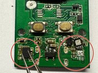
It became clear there was a poor contact somewhere, most likely near the resistors. Remembering that “most often the user himself creates the problem,” rule I checked the resistor near the upper button, which I had soldered earlier.
-
Before resoldering, its resistance was 1 kΩ. I checked it in case it had cracked while soldering. After resoldering, its resistance rose to 1.5 kΩ enough to disturb the voltage divider. I marked these resistors in blue in the photo. The desoldered one is the failed (upper) resistor; the second is the lower. Normal voltage in a middle is 1V.
-
-
-
The hardest part was behind us. Now we had to install the spare parts.
-
I soldered a 6-pin Type-C USB socket using a hot-air fan and soldering iron. Soldering was not easy because the board was difficult to heat. This caused two 3.2×4.2×2.5H mm buttons to melt, but they remained functional and can be replaced later.
-
DFN8 charger packages were IMPOSSIBLE to find, so i replaced them with a BQ24090 chip board (in other words, I did a bit of chip tuning). Board was ordered from China somewhere in past, it was called "Easy Chip Charger" (ECC), link in the article description. I attached the VCC, VBAT and GND using little wires.
-
To replace the broken 1 kΩ resistor, I reused one from the DFN-8 package connections that were no longer required.
-
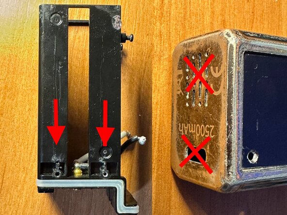
The internal battery had swollen and burst the case, preventing it from opening initially. This happened because the battery was depleted to 0 V by a short circuit and had no additional protection due to the device’s schematic design and purpose.
-
Original battery parameters: K23500D 3.7 V 9.25 Wh HTKJ 21102803AP. Dimensions: diameter ~22 mm (24 mm after swelling), length ~50–52 mm. I replaced it with an 18500 cell.
-
-
-
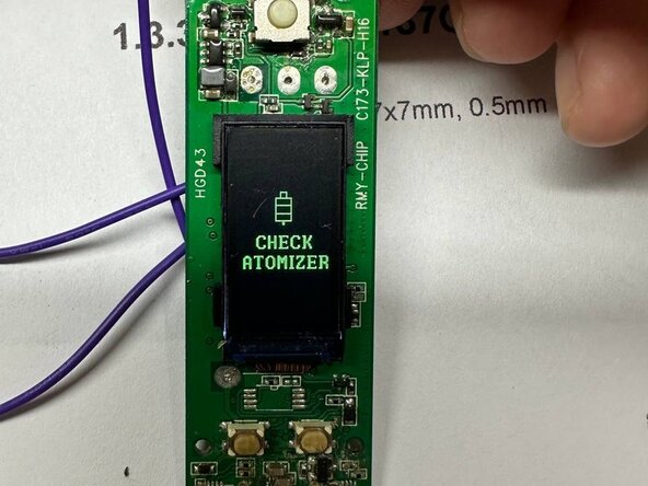
After reflow a “Check Atomizer” error appeared. When I shorted the board’s output, it showed a “Shorted” error.
-
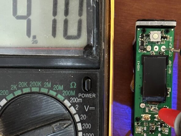
Next I tested the VBAT voltage to ensure the battery was charging. Also the blue LED on the chip board indicated that the BQ charge controller was working.
-
For output load testing I attached a bunch of ceramic 3.5R resistors to the output. The resistors heated up, proving the circuit was finally repaired.
-
-
-
Some time after assembly, the "shorted" error suddenly started to appear, or the controller simply started to reboot cyclically. The device worked from a laboratory power supply, but did not want to work from a battery.
-
This behavior was strange, but I found out that the problem was in the connection of the laboratory power supply. When I pressed the probe, I deformed the board and the error disappeared. I re-attached the board and the error disappeared. This means that there is still a bad contact somewhere, and the device may fail at any moment.
-
Soldering the microcontroller pins solved the problem, but it is not known for how long
-
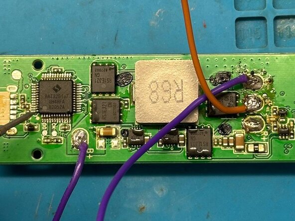
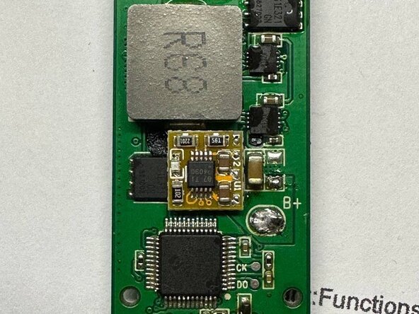
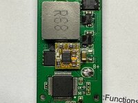
Some of the voltages showed on the test points - ceramic capacitors. I also noted the components that I examined during the repair (from both sides).
-


Repairing this device took nearly eight hours of difficult debugging. Because of the initially broken USB Type-C connector, the battery and circuit were destroyed, and the case could not be opened without breaking it. That meant complete failure of the device. I have literally rebuilt it from ashes.