crwdns2915892:0crwdne2915892:0
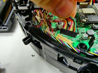
This is the replacement guide for the front caster wheel on the Shark IQ AV993 robot. When replacing the wheel remember to be careful moving parts and taking things out of the robot as some pieces are very sensitive and easy to break. Replacing the front caster wheel is necessary if it is clogged with debris and the sensors are dirty, causing the wheel to not function properly.
crwdns2942213:0crwdne2942213:0
-
-
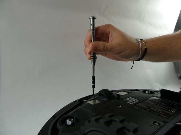
Unscrew the two 14 mm screws on the battery panel using a Phillips #1 screwdriver.
-
-
-
Gently pull the white tabs on the battery straight upward.
-
There is a clip inserted into a plastic housing via wiring. Disconnect the battery by pressing in the clip.
-
Remove the battery from the device.
-
-
-
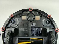
Remove the five 10 mm screws from the bottom of the device using a T15 Torx screwdriver.
-
-
-
Pry both ends of the black piece to snap it out of place.
-
-
-
Use both hands to lift the device.
-
The front bumper that is seated on the device will fall off.
-
-
-
Flip over the vacuum so that the bottom is facing upwards.
-
Remove the five 14 mm screws using a T20 Torx screwdriver.
-
-
-
Pull upward on the wheel to remove the wheel housing.
-
Press the tab on the clip and slide the wires out of the housing.
-
-
-
-
Remove the dust bin from the device by pressing down on the release button and pulling out the tray.
-
-
-
Turn the device over so the bottom is facing upwards.
-
Press on the release tabs located on the roller brush cover.
-
Remove the cover from the device.
-
-
-
Use your hands to lift the roller brush out of the device.
-
-
-
Remove the five 14 mm screws from the bottom of the device using a T20 Torx screwdriver.
-
-
-
Use your hands to lift the bottom of the vacuum away from the top plastic cover.
-
-
-
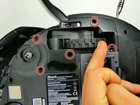
Remove the three 10 mm screws using a Phillips #1 screwdriver.
-
Off to the right and left sides of the robot you will find one clip leading to a smaller independent board. Remove the singular 9 mm screw using a T15 Torx screwdriver to free the edges of the plastic element holding the motherboard down. Repeat this for the other side.
-
Detach the white connector from the plastic housing. Repeat this for the other side.
-
-
-
Unplug each of the thirteen connectors from their housings on the motherboard.
-
-
-
Take the wires out of this clip so that the plastic cover can be free.
-
-
-
On either side of the bot, there are clips that insert into the upper plastic housing piece that hold the motherboard down. Popping these pieces off will free this covering, allowing the motherboard to be almost free.
-
-
-
Remove the two 10 mm screws using a Phillips #1 screwdriver, freeing the motherboard from the plastic holdings below the board.
-
-
-
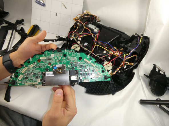
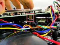
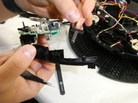
Upon lifting up the motherboard, which will lift straight up, there is a singular clip that connects the rest of the bot. Unclip this, where the clip is large enough to undo with a finger.
-
Once this is removed, the motherboard and the plastic it is clipped to can be removed from the rest of the bot.
-
-
crwdns2935267:0crwdne2935267:0Tweezers$4.99
-
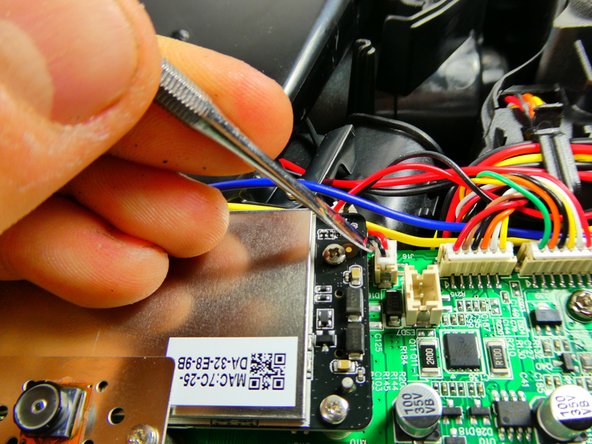
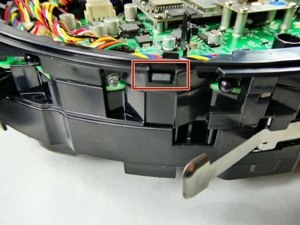
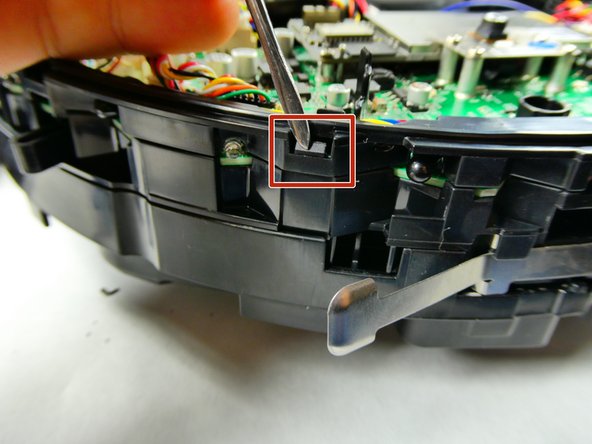
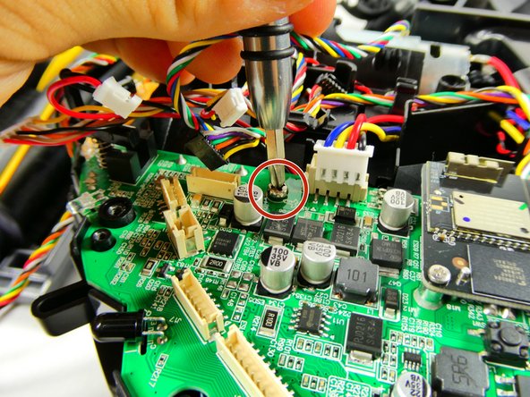
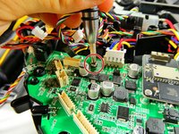
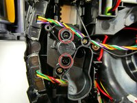
The board is attached to the plastic frame by these spring-loaded clips. Pinch the bottom of these with some tweezers and push the ends through the hole they bore to remove them.
-
-
-
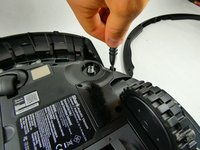
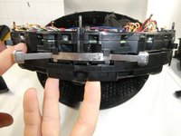
Remove two 12 mm screws using a Phillips #1 screwdriver to loosen the front caster wheel.
-
-
-
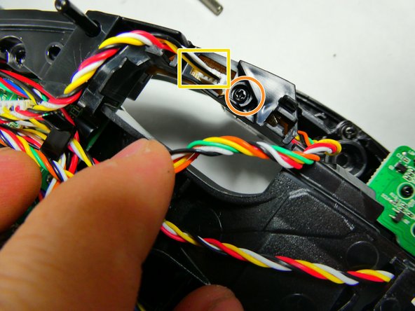
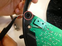
This red clip belongs on the end of the piece highlighted in orange. Once broken off, it may be advantageous to replace the whole unit, but with some bending of this metal ring, it can be maneuvered back onto this metal piece. If this is not an option, replacement is the proper route here.
-


To reassemble your device, follow these instructions in reverse order.

crwdns2935287:0crwdne2935287:0

UMass Dartmouth, Team 3-3, Botvin Fall 2022 crwdns2935289:0UMass Dartmouth, Team 3-3, Botvin Fall 2022crwdne2935289:0
UMASSD-BOTVIN-F22S3G3
crwdns2931471:03crwdne2931471:0
crwdns2935297:06crwdne2935297:0