crwdns2942213:0crwdne2942213:0
-
-
Power off and unplug the monitor before starting.
-
Place the monitor face down on a soft, flat surface (such as a towel) to protect the screen.
-
Using a Phillips #2 screwdriver, remove the four 11.5 mm screws securing the stand.
-
Gently pull the stand out to detach it from the monitor. - Caution: Do not force the stand out. If it resists, check that all screws have been fully removed before pulling.
-
-
-
Using the same Phillips #2 screwdriver, remove the two 11.5 mm screws securing the plastic bar.
-
Lift the bar away and set it aside.
-
-
-
Align the new stand and/or accessories with the mounting points on the back of the monitor.
-
Reinsert and tighten all screws securely.
-
Confirm the stand is stable and level before turning the monitor upright. - Reminder: Double-check all screws are firmly tightened and parts are properly aligned to prevent instability or tilting after reassembly.
-
-
-
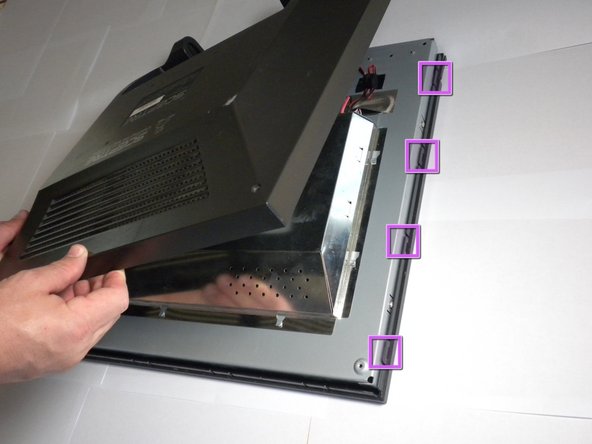
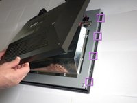
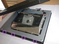
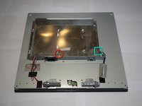
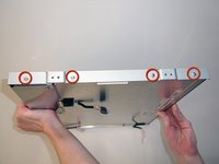
Using a #2 Phillips screwdriver, remove the six 7mm screws at the circled locations.
-
-
-
-
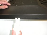
Pry the monitor using the plastic opening tool to release the clips holding the cover on.
-
Once all the clips have been released, remove the cover by pulling it up.
-
-
-
Using the #2 Phillips screwdriver, remove the one 6mm screw.
-
Unplug the indicated cable by pulling on the base.
-
Slide the cover toward the top of the monitor.
-
Remove the cover.
-
-
crwdns2935267:0crwdne2935267:0Tweezers$4.99
-
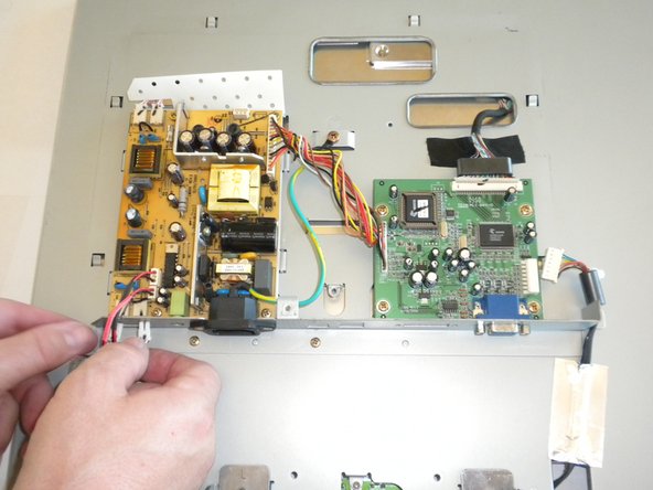
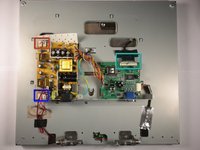
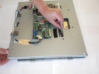
Disconnect the two connectors at the top-left of the power board.
-
Disconnect the two connectors at the very bottom of the power board (pink wire).
-
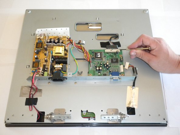
Disconnect the multi-pin connector at the top of the motherboard.
-
-
-
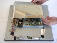
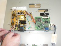
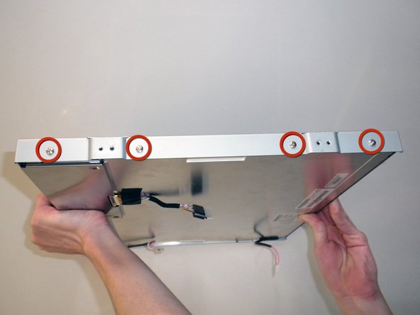
Use a #2 Phillips to unscrew the two 4.5mm screws on each side of the back panel.
-
Carefully side the connectors through their respective openings.
-
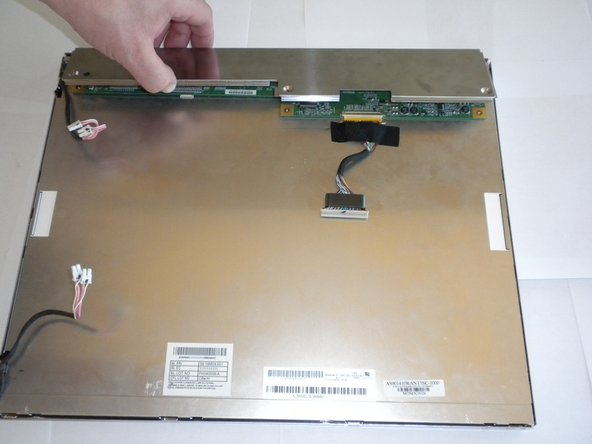
Lif the back panel to reveal the LCD back cover.
-
-
-
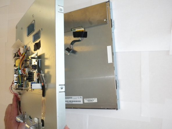
Use a #2 Phillips to remove the four 6mm screws on the bezel for each side of the back cover.
-
Remove the bezels from the LCD back cover (the bezels should simply fall off once the screws are removed).
-
-
-
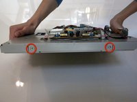
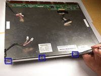
Use a #0 Phillips to remove the three 4.5mm screws located on the LCD back cover.
-
Lift the inner panel to remove it.
-
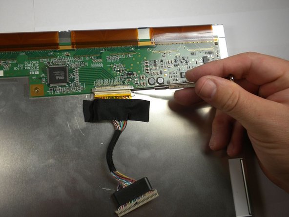
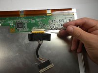
Disconnect the muti-pin connector on the LCD back cover by firmly pulling down on it.
-
-
-
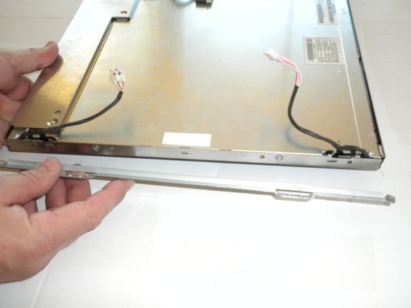
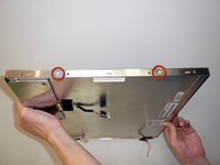
Use a #0 Phillips to remove the two 6mm screws on each side of the LCD cover.
-
There are tabs holding down the cover. You may have to use a bit of force to pry them open.
-
A small flat-blade screwdriver can be used to pry off LCD cover.
-
-
-
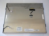
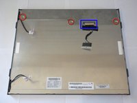
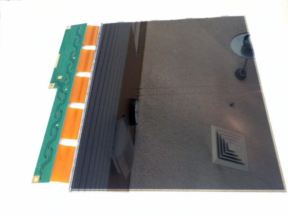
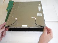
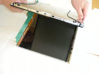
Lift the LCD back cover to reveal the LCD screen below.
-


To reassemble your device, follow these instructions in reverse order.
crwdns2935221:0crwdne2935221:0
crwdns2935227:0crwdne2935227:0
crwdns2935287:0crwdne2935287:0

Cal Poly, Team 16-56, Forte Fall 2012 crwdns2935289:0Cal Poly, Team 16-56, Forte Fall 2012crwdne2935289:0
CPSU-FORTE-F12S16G56
crwdns2931471:05crwdne2931471:0
crwdns2935297:013crwdne2935297:0