crwdns2915892:0crwdne2915892:0
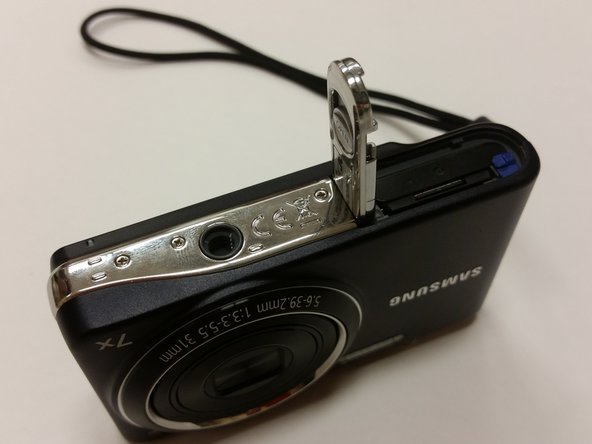
This guide allows you to replace the lens on your Samsung Pl200 camera. To complete this guide you will need a #000 Phillips Screwdriver, a Plastic Opening Tool, and a set of Tweezers.
crwdns2942213:0crwdne2942213:0
-
-
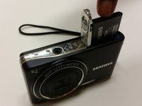
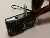
Flip Samsung PL200 over to access battery/SD card compartment on the bottom. There is a sliding release button (labeled 'OPEN') that can be slid sideways to open the battery/SD card compartment.
-
Slide this button in the direction that the arrow is pointing to release and open the spring loaded battery/SD card compartment door. Once opened, the battery should be visible.
-
-
-
Once the battery/SD card compartment is opened, in order to remove the battery, you must push the small blue release button.
-
This will release the spring loaded battery.
-
Use your fingers to remove the old battery.
-
-
-
Insert the new battery into the battery slot.
-
Push it down with your finger until the blue release switch re-engages over top of the battery.
-
Close the battery/SD card compartment.
-
-
-
Remove the six 3 mm external screws from the camera base using the Phillips #000 screwdriver.
-
-
-
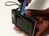
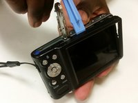
Use the plastic opening tools and your fingers to pull the external cover off.
-
-
crwdns2935267:0crwdne2935267:0Tweezers$4.99
-
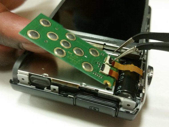
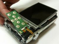
Remove the 3 mm screw holding the circuit board.
-
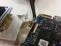
Use a pair of tweezers to detach the two ribbon cables connecting the circuit board to the camera.
-
Remove the circuit board.
-
-
-
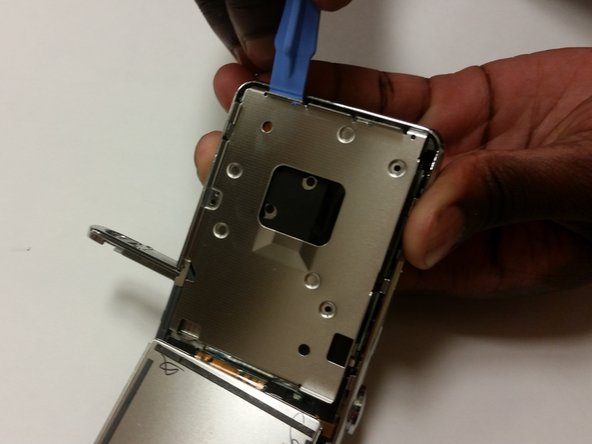
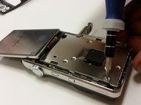
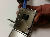
Flip the LCD screen forward and remove the two 3 mm screws holding the metal midframe using a Phillips #000 screwdriver.
-
Remove the midframe using an opening tool.
-
-
-
Remove the front cover. It will come off fairly easily.
-
-
-
-
Lift the black strip and the ribbon will easily come out.
-
After doing this, the LCD screen will be separated from the camera.
-
-
-
Push the battery cover over to access battery/SD card compartment on the bottom.
-
Slide this button in the direction that the arrow is pointing to release and open the spring loaded battery/sd compartment door.
-
-
-
Once the battery/SD card compartment is opened, simply push the SD card down to activate the spring loaded ejector to raise SD card.
-
Use your fingers to remove the old SD card.
-
Close the battery/SD card compartment.
-
-
-
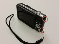
Remove the two black 3 mm screws from the right side of the camera using a Phillips #000 screwdriver.
-
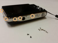
Remove the five silver 3 mm screws from the camera's side and bottom using a Phillips #000 screwdriver.
-
-
-
Use a plastic opening tool and your fingers to pry off the external cover.
-
-
crwdns2935267:0crwdne2935267:0Tweezers$4.99
-
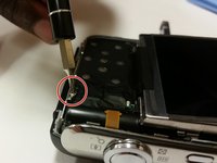
Remove the single 3 mm screw securing the circuit board with a Phillips #000 screwdriver.
-
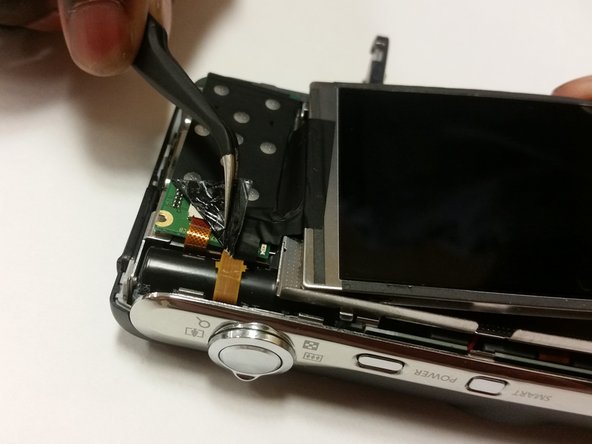
Remove any leftover tape on the circuit board and screen.
-
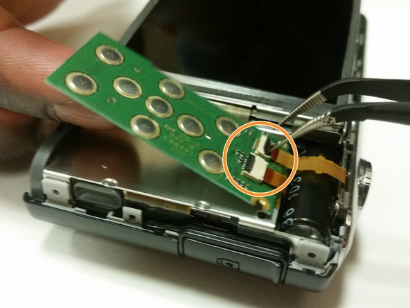
Unplug and remove the wires from the circuit board using a set of tweezers.
-
-
-
Flip the LCD screen forward and out to the side.
-
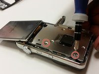
Use a Phillips #000 screwdriver to remove the two 3 mm screws beneath the LCD screen.
-
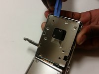
Remove the metal brace using the Plastic Opening Tool.
-
-
-
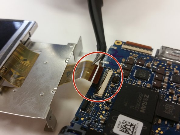
Flip the ZIF connector's locking bar vertically, then gently remove the ribbon cable.
-
Remove the screen.
-
-
-
Remove the front cover of the camera using your fingers and a plastic opening tool.
-
-
-
Set the screen and metal brace aside.
-
Open the camera’s battery compartment on the bottom part of the camera.
-
-
-
Remove the two 3 mm corner screws that secure the motherboard, with a Phillips #000 screwdriver.
-
Remove any leftover tape that may still be on the motherboard.
-
-
-
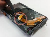
Use tweezers to remove the tape from the bottom of the camera.
-
Then use the tweezers to disconnect the lens unit cord at the bottom of the camera from the motherboard.
-
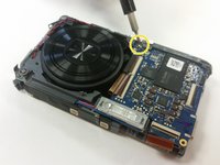
Remove the last 3 mm screw securing the motherboard with a Phillips #00 screwdriver.
-
-
-
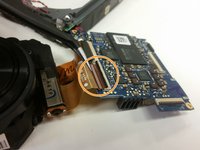
Use tweezers to unplug the small lens unit cord from the camera frame on the backside of the camera.
-
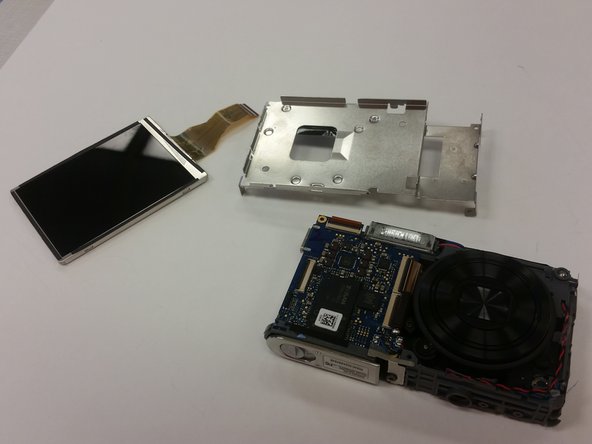
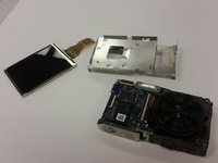
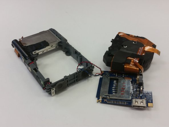
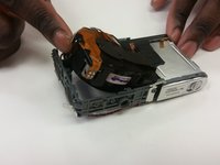
Gently lift the lens unit from the frame.
-
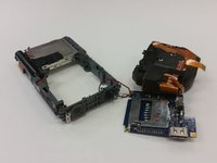
Separate the lens unit, motherboard, and camera.
-
-
-
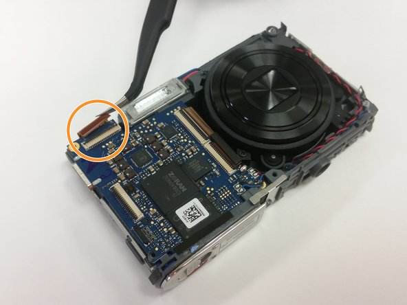
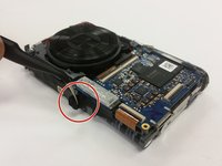
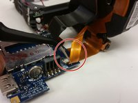
Use tweezers to disconnect the small ribbon cable from the motherboard.
-
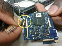
Then use the tweezers to remove the first large lens unit ribbon cable from the motherboard.
-
Finally, use the tweezers to remove the second large lens unit ribbon cable from the motherboard.
-
-
-
You have now separated the lens unit. Replace it with a functional lens unit at this stage, and reassemble the device.
-


To reassemble your device, follow these instructions in reverse order.
crwdns2935221:0crwdne2935221:0
crwdns2935229:02crwdne2935229:0
crwdns2935287:0crwdne2935287:0

Clemson, Team 15-7, Shirley Winter 2015 crwdns2935289:0Clemson, Team 15-7, Shirley Winter 2015crwdne2935289:0
CLEM-SHIRLEY-W15S15G7
crwdns2931471:05crwdne2931471:0
crwdns2935297:010crwdne2935297:0