crwdns2915892:0crwdne2915892:0
This guide will show you how to replace the jog and mode dials on the top panel assembly of the NX300.
crwdns2942213:0crwdne2942213:0
-
-
Using a Phillips #00 precision screwdriver, remove the seven 4mm screws (5 on the bottom of the device and 1 on each of the two sides) holding the back panel to the camera.
-
-
-
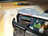
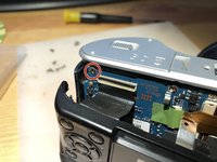
Using a Phillips #00 precision screwdriver, remove the last 4 mm screw located inside the input ports' compartment.
I've tried this before and I remember this screw not coming off why is this?
Hello Jun. If you are using the correct screwdriver, there may be a few answers to your question:
The camera screw is stuck:
This happened to the team that did this project, just keep working with the screwdriver until it comes loose.
The camera screw lost threads:
If a screw is screwed in incorrectly, it could be permanently lodged in the camera and you will be unable to open it.
The camera screw head is rounded:
If the small pieces of the head (visible) part of the screw are gone with groove marks, the screw is permanently damaged and cannot be removed unless you have special equipment.
Other than these tips, you may need to look elsewhere for more help.
-Victoria
Thank you for the quick reply! Does this have to do with it being the last screw to be taken out? do the screws have to be screwed out in this order? Thank you
Jun Hong -
There is no order for removing the screws. However, we did take note it was the most difficult to remove because of it's placement. It is difficult to get a grip on the camera when attempting to loosen this screw, therefore it is more prone to damage. Keep trying, but don't force the screw out to where the part may become damaged by means listed in the previous comment.
-Victoria
-
-
-
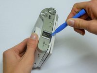
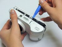
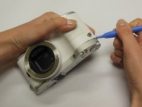
Place a plastic opening tool into the gap between the back panel and camera body, from both the top and the bottom of camera. Carefully pry open the camera and separate the back panel.
-
-
crwdns2935267:0crwdne2935267:0Tweezers$4.99
-
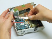
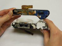
Using tweezers or your fingers, pull the display's black ribbon from the motherboard. This frees the back panel altogether.
Hi, I have follow the 4 steps and now my question is about the proper lcd screem. In my case the touch "cristal" is broke do I have to buy all the back side of the camara (with the keys, I mean) o can I take off only the "cristal". I saw in Aliexpress taht they sell all the piece or the "cristal" alone. I do not know how to take out the broken cristal from the back piece. please can you help me. Sorry by my english I am Spanish and I do not now if I did explain properly. Thank you.
How can I buy this back panel assembly?
Mail me : saroch501@gmail.com
Big thanks.
-
-
-
-
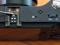
Using a Phillips #00 precision screwdriver, remove the 3mm screw holding the top panel of the camera in place. Also, remove the screws under hot shoe metal clip, otherwise you can break a piece of sensor frame leading to costly repair.
-
-
-
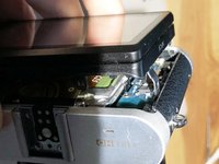
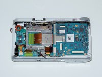
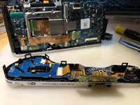
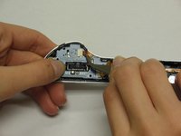
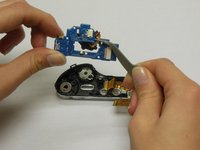
Using a plastic opening tool, carefully remove the top panel of the camera.
It's not possible to remove the top panel with just the plastic opening tool. I think there is a screw underneath the hot shoe attaching the top panel to the camera metal chassis. The photos show a broken metal tap from the camera chassis attached to the top panel metal plate. Someone must have used a lot force to break the tab and get the panel off. I stopped trying to take the panel off because I figured out the problem with my camera.
-
-
crwdns2935267:0crwdne2935267:0Tweezers$4.99
-
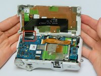
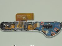
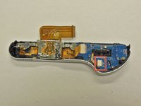
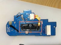
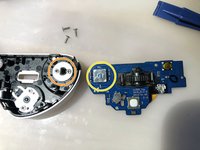
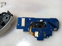
Using a Phillips #00 precision screwdriver, remove the three 4mm screws holding the power switch board in place.
-
Using tweezers, gently pull the ribbon cable out of the power switch board.
-
-
-
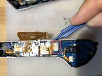
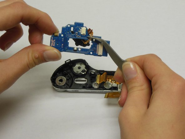
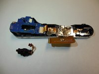
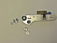
Using a Phillips #00 precision screwdriver, remove the 4mm screw holding the jog dial in place.
-
Using tweezers, gently remove the ribbon cable attached to the jog dial.
-
-
-
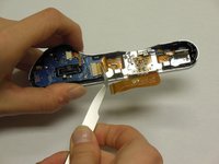
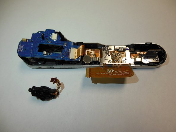
The jog dial should fall out easily. If not, use a pair of tweezers to gently poke it though the power board.
-
-
-
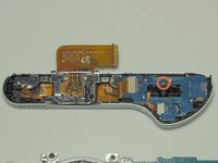
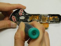
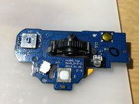
Using a Phillips #00 precision screwdriver, remove the four 3mm screws holding the mode dial and power switch/shutter button in place.
-
Remove the metal mounts from the underside of the dials. The dials are now free from the camera.
-


To reassemble your device, follow these instructions in reverse order.
To reassemble your device, follow these instructions in reverse order.
crwdns2935221:0crwdne2935221:0
crwdns2935229:011crwdne2935229:0

crwdns2915084:0crwdne2915084:0

USF Tampa, Team 9-6, Blackwell Winter 2015 crwdns2935289:0USF Tampa, Team 9-6, Blackwell Winter 2015crwdne2935289:0
USFT-BLACKWELL-W15S9G6
crwdns2931471:04crwdne2931471:0
crwdns2935297:010crwdne2935297:0
crwdns2947412:03crwdne2947412:0
Thanks, this was useful. Camera was switching modes randomly. I didn't replace the PCB however, just opened and sprayed a lot of silicon oil into the dial.
Thanks! I fixed my camera. But i think step 10 not necessary.
Perfect ! My Camera was switching modes randomly too. I changed the board from step 9 with a new part found on Ebay. Thank you :-)