crwdns2915892:0crwdne2915892:0
This guide will show you how to remove the flash assembly in the Samsung NX Mini. The flash assembly includes the capacitor, so be sure to discharge the capacitor prior to removal. Learn more about discharging capacitors here.
crwdns2942213:0crwdne2942213:0
-
-
Orient the camera so the button panel and LCD are facing you.
-
Use a spudger or fingernail to open the battery compartment on the right side of the camera.
-
-
-
Push the blue trapdoor to the left to release the battery, and remove the battery.
-
-
-
Use a Phillips #00 screwdriver to remove the 4 mm screw inside the battery compartment.
-
-
-
Remove the 4 mm Phillips #00 screw hiding in the external flash port.
-
-
-
Remove the four 5 mm Phillips #00 screws from the lens assembly.
-
-
crwdns2935267:0crwdne2935267:0Tweezers$4.99
-
Remove the metal lens mount by hand or with tweezers.
-
-
-
Use tweezers to remove the inner metal ring.
-
-
-
Use a Phillips #00 screwdriver to remove the three 4 mm screws from the bottom of the case.
-
-
-
-
Use your hands to slowly pull the front casing away from the camera.
-
-
crwdns2935267:0crwdne2935267:0Tweezers$4.99
-
Gently flip the sensor cover back to expose the screw attaching the sensor cover to the ribbon cable.
-
Use a Phillips #00 screwdriver to remove the 3 mm screw from the sensor cover.
-
Use tweezers to remove the metal contact cover. Be sure to carefully remove the cover so the gold contacts remain in place.
-
-
-
Remove the four 4 mm Phillips #00 screws holding the sensor mount in place.
-
-
-
Remove the four 4 mm Phillips #00 screws securing the battery compartment to the mother board.
-
Remove the battery compartment.
-
-
-
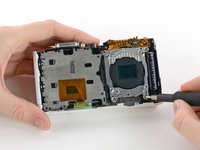
Use a spudger to disconnect the ribbon cable connecting the image sensor to the motherboard.
-
-
-
Gently remove the sensor mount from the camera case.
-
-
-
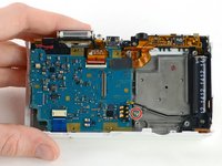
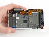
Use a Phillips #00 screwdriver to remove the 3 mm screw located below the wifi antenna.
-
-
crwdns2935267:0crwdne2935267:0Tweezers$4.99
-
Use tweezers to disconnect the wifi antenna from the motherboard.
-
-
-
Use a spudger to disconnect the LCD ribbon cable by prying it straight up from the motherboard.
-
-
-
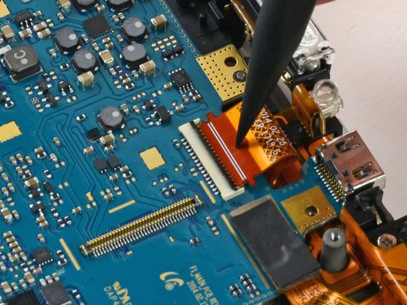
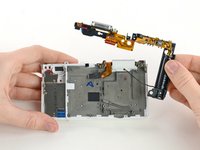
Use a spudger to unlock the topmost ZIF connector by flipping open the black flap.
-
-
-
Insert the pointed end of a spudger into the hole in the middle of the ribbon cable.
-
Gently pull the spudger back to slide the ribbon cable out of its connector.
-
-
-
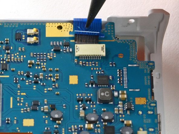
Disconnect the blue ribbon cable from the motherboard.
-
Insert the pointed end of a spudger into the hole in the top of the ribbon.
-
Gently pull the ribbon from the connector.
-
-
-
Remove the motherboard from the camera.
-
-
-
Use a Phillips #00 screwdriver to remove the two 5 mm screws holding the flash assembly to the camera case.
-
-
-
Remove the flash assembly by gently pulling it away from the case.
-


To reassemble your device, follow these instructions in reverse order.
