crwdns2915892:0crwdne2915892:0
Use this guide to replace the headphone jack assembly, including the status light and infrared sensor, in your Samsung Galaxy S4.
crwdns2942213:0crwdne2942213:0
-
-
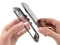
Pry with a plastic opening tool, or your fingernail, in the divot to the left of the rear-facing camera, near the power button.
-
-
-
Lift the rear case by the corner nearest the divot and remove it from the phone.
-
-
-
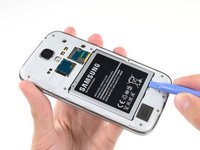
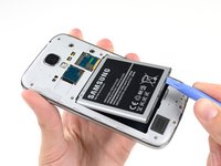
Insert a plastic opening tool, or your finger, into the notch of the battery compartment and lift the battery upward.
-
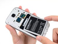
Remove the battery from your phone.
-
-
-
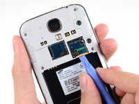
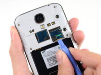
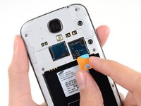
Use a plastic opening tool, or your fingernail, to press the SIM card slightly deeper into its slot until you hear a click.
-
After the click, release the card and it will pop out of its slot.
-
Remove the SIM card.
-
-
-
Remove the nine 4.0 mm Phillips #00 screws securing the midframe to the display assembly.
-
-
-
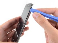
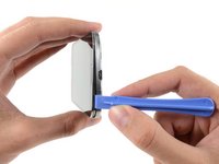
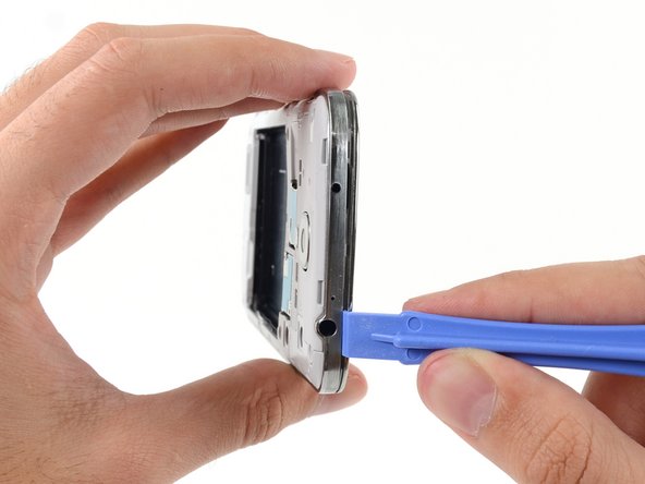
Starting on the volume button side of the phone, insert your plastic opening tool between the chrome bezel around the display glass and the larger chrome border piece. Look for the seam between the two.
-
Slide the opening tool along the seam, separating the plastic clips as you go.
-
-
-
-
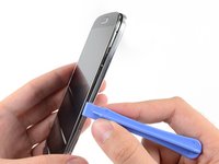
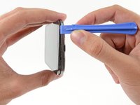
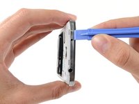
Continue prying around the corner of the phone.
-
Slide your opening tool along the seam between the midframe and display along the bottom of the device, releasing more of the plastic clips.
-
-
-
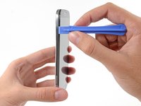
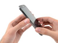
Again, pry around the corner, to the power button side.
-
Slide the opening tool along the seam.
-
-
-
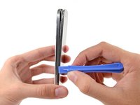
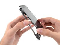
Continue sliding the opening tool around the top of the phone, releasing the last of the clips and freeing the midframe from the display assembly.
-
-
-
Remove the midframe from the display assembly.
-
-
-
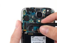
Use the flat end of a spudger to disconnect the USB board connector.
-
Disconnect the front-facing camera cable connector.
-
Disconnect the earpiece speaker assembly cable connector.
-
-
-
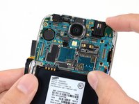
Disconnect the headphone jack assembly cable connector.
-
Disconnect the display/digitizer cable connector.
-
Disconnect the antenna cable connector.
-
-
-
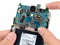
Remove the single 2.4 mm Phillips #00 screw from the motherboard assembly.
-
-
-
Remove the single 2.4 mm Phillips #00 screw securing the headphone jack assembly to the display assembly.
-


To reassemble your device, follow these instructions in reverse order.
crwdns2935221:0crwdne2935221:0
crwdns2935229:037crwdne2935229:0


crwdns2947412:08crwdne2947412:0
I accidentally inserted an electric pin instead of the auxiliary jack into the head phone jack assembly. There was a loud screeching sound and ever since then the head phones do not work. However, I can play music through the phone speaker and also with Bluetooth. I cannot listen to music with my ear buds or head phones or with auxiliary speakers. I have replaced the jack assembly with a new one and yet it is the same. What more can I do to rectify this?
Did you ever get help on this? Having the same problem.
Me too have same problem....did u got it fixed or not?...if yes how u did it...?
reone -
I too am having this issue. I assume we have fried the amp for external audio with wtv current we happened to let touch our aux ports. Sounds like I bigger issue to fix. Just still wondering if I can.
Where do you even get the part?