crwdns2915892:0crwdne2915892:0
The display is a 5 inch in size and with a resolution of 720x1280 pixels. And it is a touchscreen.
crwdns2942213:0crwdne2942213:0
-
-
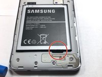
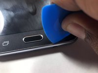
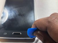
Locate the side notch that allows you to open the back casing.
-
-
-
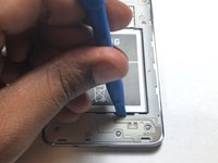
Use a plastic prying tool or your fingernail to pop the back cover off of the phone.
-
-
-
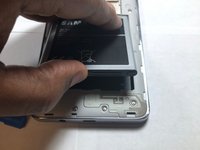
Locate the battery notch and remove the battery, using either your finger or a plastic prying tool.
-
-
-
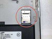
Use a plastic pry tool to slide both of the cards out.
-
-
-
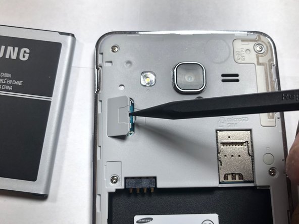
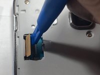
Use the plastic Spudger tool to pry open the LCD ribbon cable cover.
-
-
-
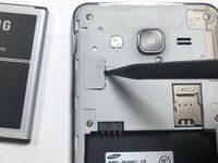
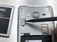
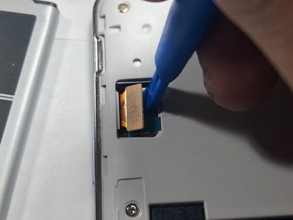
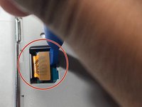
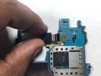
Using a plastic pry tool, carefully pry the LCD ribbon cable from the logic board.
-
-
-
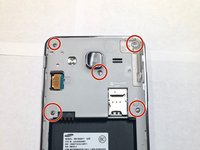
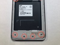
Take a Phillips #00 head and remove all 9 screws. Once done place them aside where you won't lose them.
-
-
-
-
Use an iFixit plastic pick to pry away the LCD from the back assembly.
-
-
-
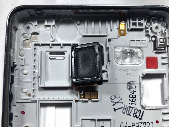
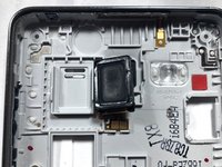
Once both the LCD and back assembly come apart, look at the back assembly where the speaker is located.
-
Once located, take the plastic pry tool to remove the speaker from its housing and replace it with a new one.
-
-
-
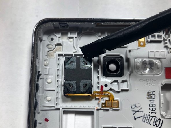
Use a plastic pry tool to lift the front-facing camera from its housing.
-
-
-
Once the camera is out of the housing, disconnect the camera from the logic board.
-
-
-
You have now sucessfully removed the front-facing camera.
-
-
-
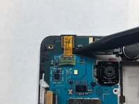
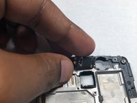
Using a Phillips #00 screwdriver, remove the screw securing the rear-facing camera.
-
-
-
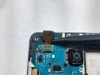
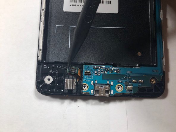
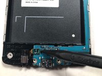
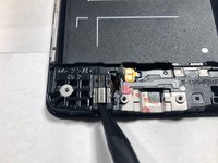
Use a plastic pry tool to disconnect the headphone ribbon from the motherboard.
-
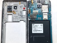
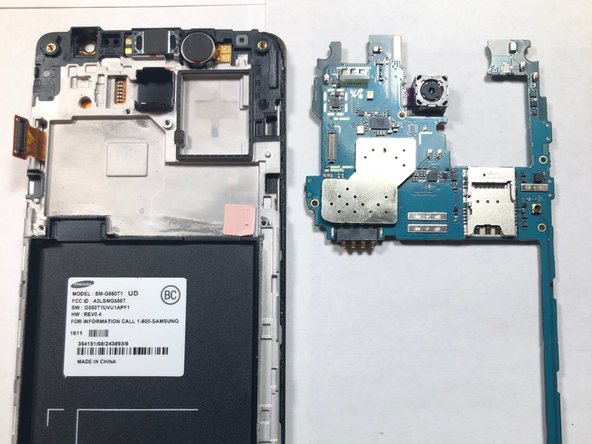
Remove the motherboard from the LCD housing by lifting up from the ends of the logic board.
-
-
-
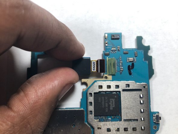
Flip the logic board so the camera lens is facing down rather than at you.
-
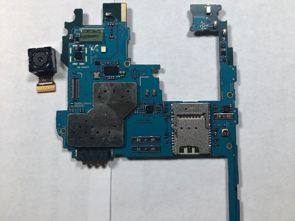
Use your finger to remove the camera from its connection on the logic board.
-
-
-
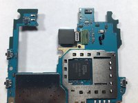
Once the logic board is stripped of the cameras, replace the logic board.
-
-
-
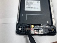
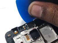
Take a plastic stick to insert into the headphone jack to lift part of the housing.
-
Once that's complete place the part aside.
-
-
-
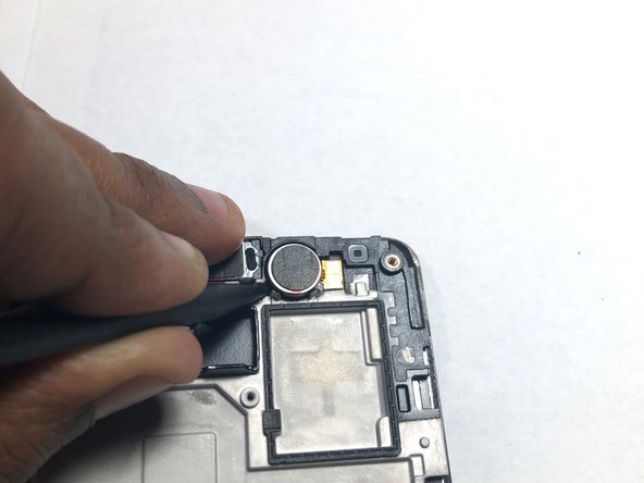
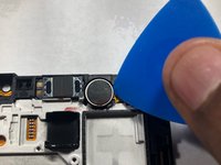
Next take the same tool to remove the phones vibrator out its housing.
-
-
-
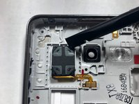
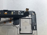
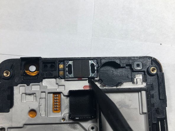
Lastly, take out the ear piece out of its housing using a plastic pry tool.
-
-
-
Now since all three parts are taken out of its place take those part and place them onto the new LCD screen.
-


To reassemble your device, follow these instructions in reverse order.
To reassemble your device, follow these instructions in reverse order.
crwdns2935221:0crwdne2935221:0
crwdns2935229:010crwdne2935229:0

crwdns2915084:0crwdne2915084:0

Gateway, Team S1-G5, Luster Fall 2018 crwdns2935289:0Gateway, Team S1-G5, Luster Fall 2018crwdne2935289:0
GCC-LUSTER-F18S1G5
crwdns2934841:01crwdne2934841:0
crwdns2935297:05crwdne2935297:0