crwdns2915892:0crwdne2915892:0
Use this guide to replace the rear-facing camera assembly in your Samsung Galaxy Note II.
crwdns2942213:0crwdne2942213:0
-
-
Grasp the end of the stylus and remove it from its slot in the midframe.
-
-
-
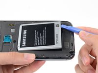
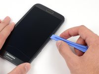
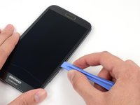
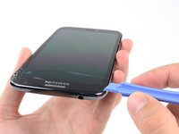
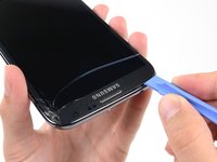
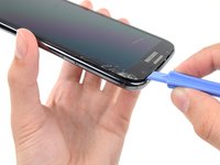
Pry with a plastic opening tool, or your fingernail, in the divot to the left of the rear-facing camera, near the power button.
-
-
-
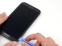
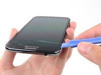
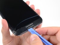
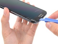
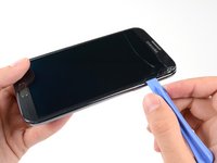
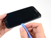
Lift the rear case by the corner nearest the divot and remove it from the phone.
-
-
-
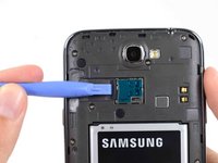
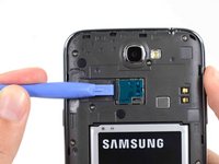
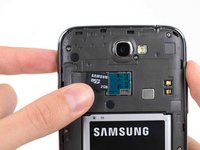
If you have an SD card inserted, use the flat end of a spudger, or your fingernail, to press the microSD card slightly deeper into its slot until you hear a click.
-
After the click, release the card and it will pop out of its slot.
-
Remove the microSD card.
-
-
-
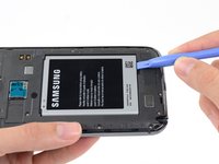
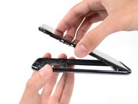
Insert a plastic opening tool, or your finger, into the notch of the battery compartment and lift the battery upward.
-
-
-
Remove the battery from the midframe.
-
-
-
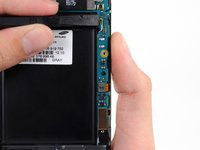
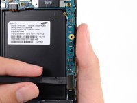
Remove the eleven 4.0 mm Phillips #00 screws securing the midframe to the display assembly.
-
-
-
-
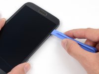
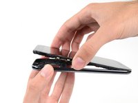
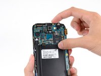
Insert your plastic opening tool between the midframe and front panel assembly on the side of the phone.
-
Slide the plastic opening tool down the seam.
-
-
-
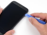
Continue to run the plastic opening tool down the seam.
-
-
-
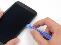
Carefully pry around the corner with a plastic opening tool.
-
-
-
Pry along the top of the phone with a plastic opening tool.
-
-
-
Push the plastic opening tool down to free the corner of the midframe from the display assembly.
-
-
-
Free the clips along the power button side of the phone.
-
Lastly, free the two clips along the top and bottom edge of battery compartment.
-
-
-
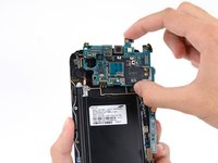
Lift the display assembly out of the midframe.
-
-
-
Use a spudger to disconnect the vibrator/power button assembly cable connector.
-
Disconnect the antenna cable connector.
-
Disconnect the display cable connector.
-
-
-
Disconnect the front-facing camera cable connector.
-
Disconnect the headphone jack cable connector.
-
Disconnect the digitizer cable connector.
-
-
-
Use the spudger to disconnect the antenna cable connector from the motherboard.
-
Disconnect the soft button cable connector.
-
Disconnect the USB board cable connector.
-
-
-
Remove the 3 mm Phillips #00 screw securing the motherboard to the display assembly.
-
-
-
Use a spudger to disconnect the rear-facing camera assembly cable connector.
-
-
crwdns2935267:0crwdne2935267:0Tweezers$4.99
-
Use tweezers, or your fingers, to remove the rear-facing camera assembly.
-


To reassemble your device, follow these instructions in reverse order.
crwdns2935221:0crwdne2935221:0
crwdns2935229:013crwdne2935229:0

