crwdns2915892:0crwdne2915892:0
Use this guide to replace the front panel display assembly on your Samsung Galaxy Note II.
crwdns2942213:0crwdne2942213:0
-
-
-
Grasp the end of the stylus and remove it from its slot in the midframe.
 crwdns2952109:0crwdne2952109:0
-
-
-
-
-
Pry with a plastic opening tool, or your fingernail, in the divot to the left of the rear-facing camera, near the power button.
-
-
-
Lift the rear case by the corner nearest the divot and remove it from the phone.
-
-
-
-
-
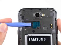
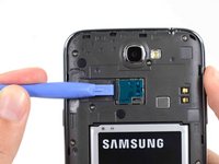
If you have an SD card inserted, use the flat end of a spudger, or your fingernail, to press the microSD card slightly deeper into its slot until you hear a click.
-
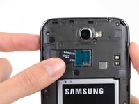
After the click, release the card and it will pop out of its slot.
-
Remove the microSD card.
-
-
-
-
-
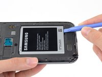
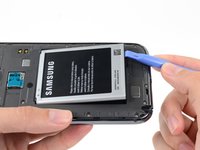
Insert a plastic opening tool, or your finger, into the notch of the battery compartment and lift the battery upward.
-
-
-
Remove the battery from the midframe.
-
-
-
-
-
Remove the eleven 4.0 mm Phillips #00 screws securing the midframe to the display assembly.
-
-
-
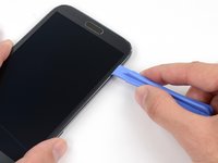
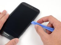
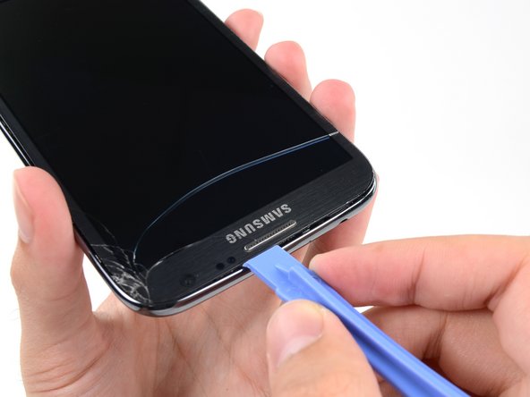
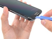
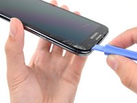
Insert your plastic opening tool between the midframe and front panel assembly on the side of the phone.
-
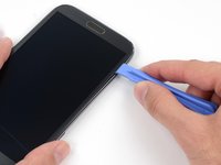
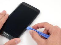
Slide the plastic opening tool down the seam.
-
-
-
Continue to run the plastic opening tool down the seam.
-
-
-
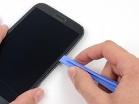
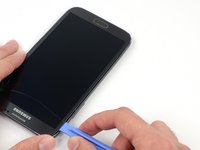
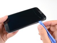
Carefully pry around the corner with a plastic opening tool.
-
-
-
Pry along the top of the phone with a plastic opening tool.
-
-
-
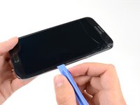
Push the plastic opening tool down to free the corner of the midframe from the display assembly.
-
-
-
-
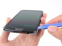
Free the clips along the power button side of the phone.
-
Lastly, free the two clips along the top and bottom edge of battery compartment.
-
-
-
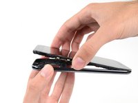
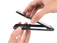
Lift the display assembly out of the midframe.
-
-
-
-
-
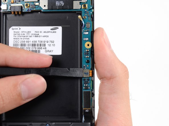
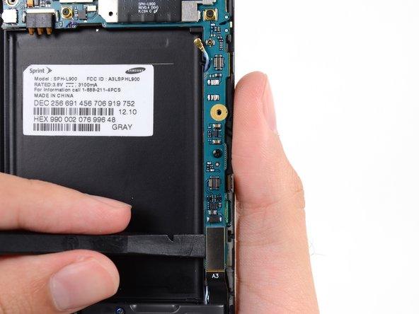
Use a spudger to disconnect the vibrator/power button assembly cable connector.
-
Disconnect the antenna cable connector.
-
Disconnect the display cable connector.
-
-
-
Disconnect the front-facing camera cable connector.
-
Disconnect the headphone jack cable connector.
-
Disconnect the digitizer cable connector.
-
-
-
Use the spudger to disconnect the antenna cable connector from the motherboard.
-
Disconnect the soft button cable connector.
-
Disconnect the USB board cable connector.
-
-
-
Remove the 3 mm Phillips #00 screw securing the motherboard to the display assembly.
-
-
-
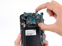
Gently remove the motherboard.
-
-
-
-
-
Remove the 3 mm Phillips #00 screw securing the headphone jack assembly to the display assembly.
-
-
-
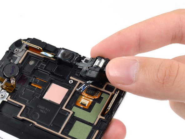
Grasp the headphone jack portion of the assembly and lift it out of its groove in the display assembly.
-
-
-
Gently pull the headphone jack straight up without twisting the cable to remove the earpiece speaker portion from its recess.
-
-
-
-
-
Remove the 3mm Phillips #00 screw from the front-facing camera bracket.
-
-
-
Remove the front-facing camera bracket.
-
-
-
Remove the front-facing camera.
-
-
-
Remove the 3 mm Phillips #00 screw securing the antenna board to the display assembly.
-
-
-
Insert the tip of a spudger under the antenna board to free it from the adhesive holding it to the display assembly.
-
-
-
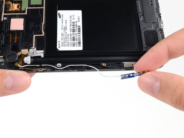
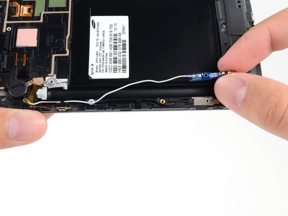
Gently de-route the antenna cable from its channel in the display assembly.
-
-
-
Remove the antenna cable from the display assembly.
-
-
-
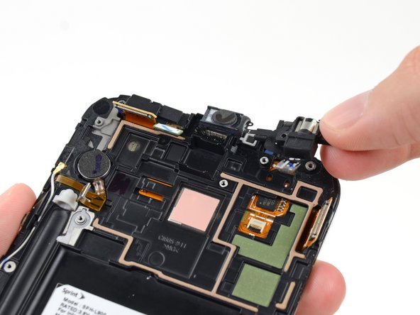
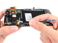
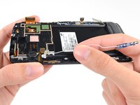
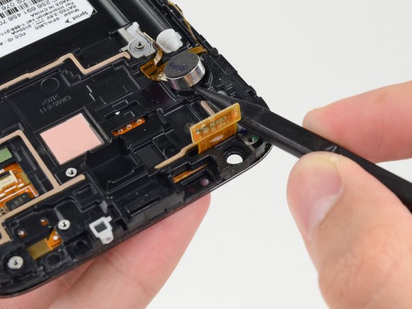
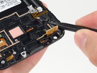
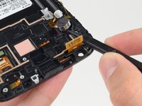
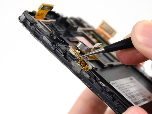
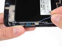
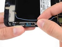
Insert the tip of a spudger under the vibrator to free it from the adhesive holding it to the display assembly.
-
-
crwdns2935267:0crwdne2935267:0Tweezers$4.99
-
Use tweezers to detach the power button from the adhesive securing it to the display assembly.
-
Remove the vibrator/power button assembly from the display assembly.
-
-
-
Remove the 3 mm Phillips #00 from the speaker enclosure.
-
-
-
Remove the speaker enclosure.
-
-
-
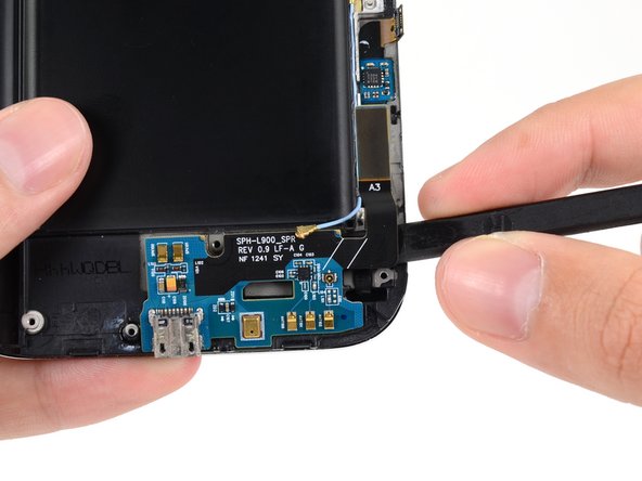
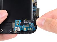
Use the flat end of a spudger to disconnect the antenna cable connector from the USB board.
-
-
-
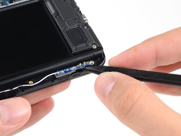
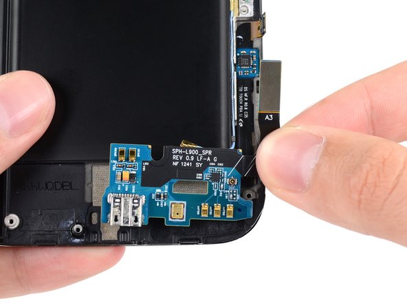
Push the flat end of a spudger under the USB board to separate it from the display assembly.
-
Remove the USB board from the display assembly.
-
-
-
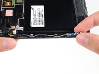
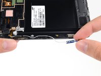
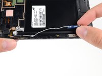
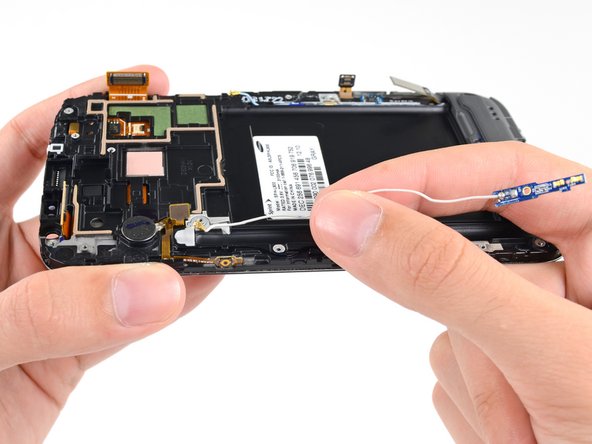
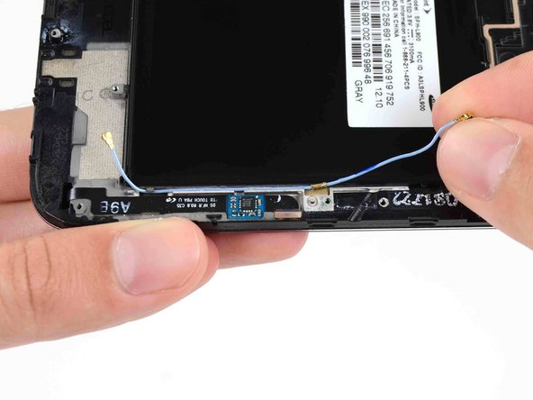
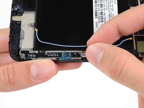
Gently deroute the antenna cable from its notch in the display assembly.
-
Remove the antenna cable.
-
-



















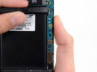
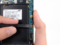
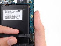


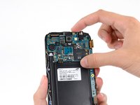













To reassemble your device, follow these instructions in reverse order.
crwdns2935221:0crwdne2935221:0
crwdns2935229:0183crwdne2935229:0


crwdns2947412:012crwdne2947412:0
This guide is awful. Not even the US phone model. mine and most on youtube does not have the antennae on both side, only a antena on one of the sides of the phone.
Also this does not cover how to remove most things that you HAVE to remove when you buy the digitizer+lcd from here... not to mention that it stops in the middle...
there is a video on youtube from https://www.youtube.com/user/LE55ONS that shows how to dismantle the note2 in much more detail than this... and he goes all the way and show how to remove every piece needed.
gcb - crwdns2934203:0crwdne2934203:0 crwdns2950251:0crwdne2950251:0
thx for the video!
note i was repairing looked slightly different. no antenna on the left and powerbutton/vibrator where differnet parts, midframe is hold by 2 additional tabs inside battery compartment. video was a good addition to this guid, and helped alot ;)
Lego - crwdns2934203:0crwdne2934203:0 crwdns2950251:0crwdne2950251:0
Thank you for the link to the videos, it helped particularly for the vibrator and power button.
anonymous 4780 - crwdns2934203:0crwdne2934203:0 crwdns2950251:0crwdne2950251:0
This is the Sprint model, SPH-L900. It's not his fault that your phone is different.
Roger - crwdns2934203:0crwdne2934203:0 crwdns2950251:0crwdne2950251:0
This guide showed me how to take mine apart in ten minutes every step was included in this guide...dont know what phone you have^^^^but this is a great guide
chad - crwdns2934203:0crwdne2934203:0 crwdns2950251:0crwdne2950251:0
