crwdns2915892:0crwdne2915892:0
Use this guide to remove and replace the motor on your Ryobi P517 reciprocating saw.
The motor is the source that powers the cutting mechanism of the saw. The motor moves the reciprocating mechanism of the saw, which converts the rotational motion of the motor to linear, reciprocating motion. The saw blade then moves in this reciprocating motion to allow for cutting. The motor’s variable speed capability allows for greater control over cutting. The motor needs to be replaced when it fails due to use, overheating, or electrical issues. Additionally, if the motor is physically damaged due to misuse or improper storage, it will need to be replaced. A poorly installed motor can interfere with the saw’s cutting power and efficiency.
Before reading this guide, please review the Ryobi P517 Troubleshooting Page to ensure that your issue cannot be resolved externally, without removing the motor. Remove the housing assembly before beginning the motor removal process.
crwdns2942213:0crwdne2942213:0
-
-
Position the saw so you can access the button-clips on both sides of the battery.
-
-
-
Press and hold the button-clip on both sides and take the battery out.
-
-
-
Lay the saw flat so the left side is facing up.
-
Remove the grey orbital button by twisting it counterclockwise.
-
-
-
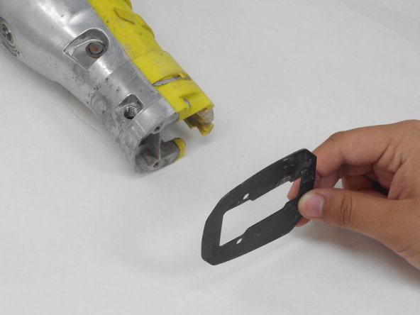
Remove the rubber boot from the device by peeling it from back to front.
-
-
-
Flip the saw so its right side is facing up.
-
Remove the 10 mm screw using a Torx T27H screwdriver.
-
-
-
Grab the black shoe assembly and pull it out from the front of the saw.
-
-
-
-
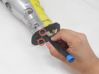
Remove the two 12.5 mm screws from the front of the guide plate using the Torx T10H screwdriver.
-
Then remove the guide plate.
-
-
-
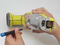
Flip the saw so its right side is facing up.
-
Use the Torx T15H screwdriver to remove the eleven 18.1 mm screws from the housing assembly.
-
-
-
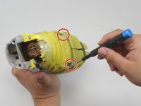
Use a Torx T15H screwdriver to remove the four 30.7 mm screws that are holding the housing assembly with the gear case assembly and gear case cover.
-
-
-
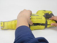
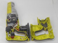
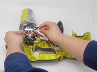
Pull apart the two sides of the housing.
-
-
-
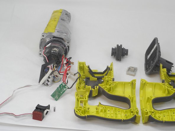
Remove the switch, circuit board, and contact plate holder assembly from the housing assembly.
-
-
-
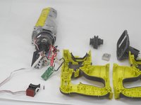
Lift and remove the gear case from the housing assembly and ensure that there are no parts remaining in housing assembly.
-
-
-
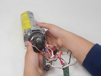
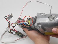
Position the saw so the ports connecting the circuit board assembly to the motor are accessible.
-
-
-
Use the soldering iron and desoldering pump to desolder the circuit board assembly from the motor.
-
-
-
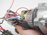
Gently pull the thin red and white wire on opposite ends of its connector to disconnect the LED from the circuit board.
-
-
-
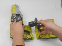
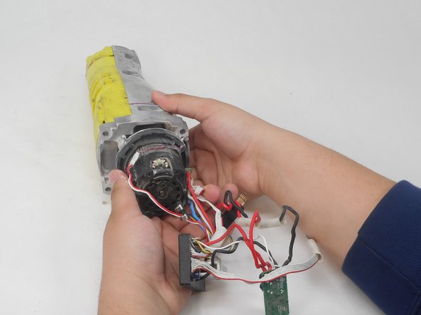
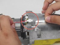
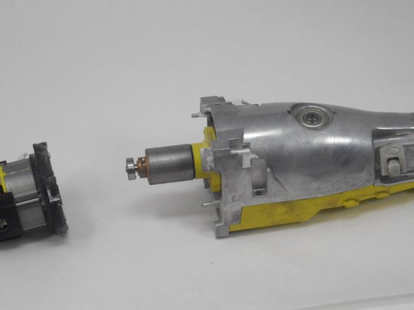
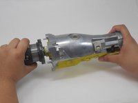
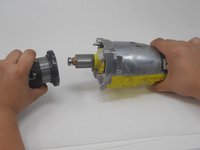
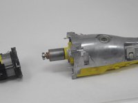
Firmly grasp the motor in one hand while holding the gear case in your opposite hand.
-
Disconnect the motor from the gear case by firmly pulling the two pieces apart.
-


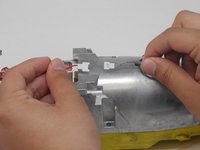


To reassemble your device, follow these instructions in reverse order.
crwdns2935221:0crwdne2935221:0
crwdns2935227:0crwdne2935227:0

crwdns2935287:0crwdne2935287:0

University of Memphis, Team 4-4, Sneed Spring 2024 crwdns2935289:0University of Memphis, Team 4-4, Sneed Spring 2024crwdne2935289:0
UM-SNEED-S24S4G4
crwdns2931471:04crwdne2931471:0
crwdns2935297:04crwdne2935297:0