crwdns2915892:0crwdne2915892:0
The trigger is a multi-speed switch and requires replacing the whole assembly. Soldering is necessary for this guide. Please familiarize yourself with the iFixit guide on Soldering before starting.
crwdns2942213:0crwdne2942213:0
-
-
Use the flat side of a metal spudger to peel the black rubber cover off of the casing.
-
Rotate the casing until it fits onto the housing with no gaps between it and the clear cover.
-
-
-
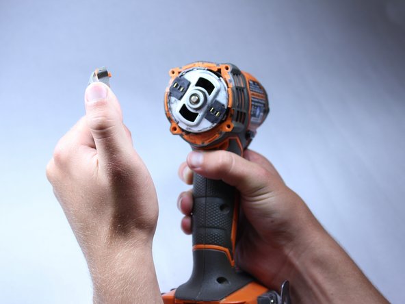
Remove the plastic cover with your hands. It should come off fairly easily.
-
-
-
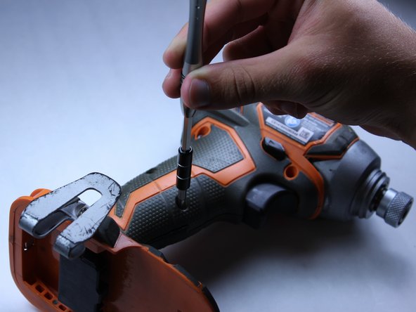
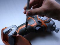
Unscrew the four 16 mm long screws from the back panel with a T10 Torx Screwdriver.
-
Use a firm grip to peel off the back panel. It is sealed tight and requires a good amount of force to remove.
-
-
-
Unscrew the eight 15 mm T10 Torx screws from the housing
-
-
-
-
Pry apart the two halves of the housing at the back side of the driver using the metal spudger. The housing is easier to remove if you pry from both sides.
-
-
-
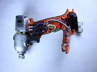
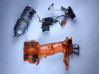
Pull out all electrical components from housing by hand. The components should require little force to lift out.
-
Lift out the motor.
-
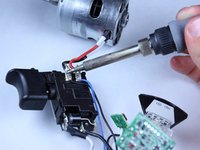
Follow the wires.
-
-
-
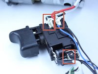
Use the soldering iron to desolder and remove the red, blue, and three black wires.
-
-
-
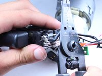
Use the wire cutters to cut the white wire, as close to the terminal on the trigger assembly as possible.
-
-
-
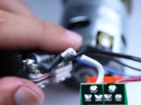
Using 16 gauge wire strippers, strip about one quarter inch off both the white wire of your new trigger assembly, and the white wire coming out of the translucent orange fuse.
-
-
-
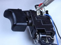
Solder the red, blue, and three black wires to their respective spots on the new trigger assembly.
-
-
-
Solder the two loose ends of the white wires together.
-
Wrap the joint with electrical tape, to ensure that the circuit doesn't short.
-


To reassemble your device, follow steps one through seven in reverse order.
To reassemble your device, follow steps one through seven in reverse order.

crwdns2915084:0crwdne2915084:0

Cal Poly, Team 15-5, Amido Spring 2015 crwdns2935289:0Cal Poly, Team 15-5, Amido Spring 2015crwdne2935289:0
CPSU-AMIDO-S15S15G5
crwdns2931471:04crwdne2931471:0
crwdns2935297:012crwdne2935297:0