crwdns2915892:0crwdne2915892:0
Use this guide to replace the logic board in your Retina MacBook 2016.
crwdns2942213:0crwdne2942213:0
-
crwdns2935267:0crwdne2935267:0Magnetic Project Mat$19.95
-
Remove the following eight screws securing the lower case:
-
Two 1.8 mm P5 Pentalobe screws
-
Four 2.9 mm P5 Pentalobe screws
-
Two 6.1 mm P5 Pentalobe screws
-
-
-
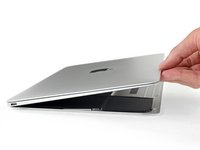
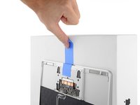
Wedge your fingers between the upper case and the lower case, starting from the rear of the MacBook between the hinges.
-
Keeping a firm grip, lift steadily until the lower case separates slightly from the upper case.
-
-
-
While holding the lower case in place, carefully flip the MacBook over so the Apple logo faces up.
-
-
-
Lift the upper case and display together from the front edge and raise it to about a 45˚ angle.
-
-
-
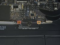
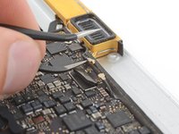
Use the flat end of a spudger to press and hold the small gold 'battery disconnect' button.
-
If the power LED is lit up, continue holding the button until the LED goes dark, and then release. This may take up to 10 seconds.
-
If the LED does not light, release the button after 5-10 seconds. Press and hold it again for 5-10 seconds, and release. Finally, press and hold it a third time for 5-10 seconds, and release.
-
-
-
Close the MacBook and carefully flip it upside-down.
-
-
-
Lifting from the front edge, open the lower case to an angle of about 45°.
-
-
crwdns2935267:0crwdne2935267:0Tweezers$4.99
-
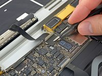
Use tweezers to peel back the tape covering the trackpad cable ZIF connector.
-
-
-
Use a spudger to carefully flip up the retaining flap on the trackpad cable ZIF connector.
-
-
-
Disconnect the trackpad ribbon cable from the trackpad by pulling it gently through its slot in the frame.
-
-
-
Carefully close the MacBook and flip it over once again, so that the Apple logo faces up.
-
Lifting from the front edge, raise the upper case/display assembly to about a 90° angle, and prop it up against something sturdy so you don't have to hold it.
-
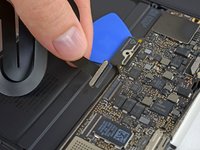
Add a piece of tape near the track pad to secure the upper case and prevent accidental movement.
-
-
-
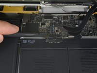
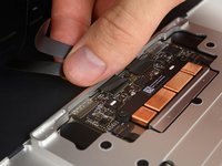
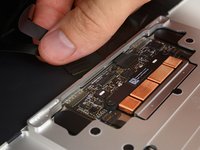
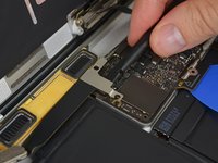
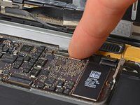
Remove the single 2.9 mm T5 Torx screw securing the battery connector to the logic board.
-
-
-
crwdns2935267:0crwdne2935267:0Battery Blocker$3.99
-
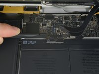
As an added precaution, you may physically disconnect the battery by inserting a battery isolation pick between the logic board and the battery connector.
-
-
-
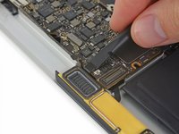
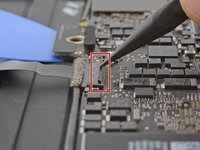
Remove the two screws securing the USB-C port cable bracket:
-
1.1 mm Phillips #00 screw
-
3.5 mm T5 Torx screw
-
-
-
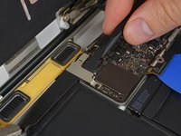
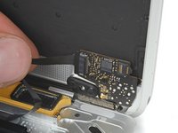
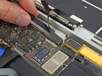
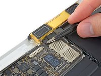
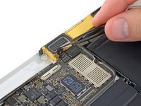
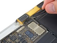
Use the flat end of a spudger to disconnect the USB-C port cable bracket by prying it straight up from the logic board.
-
-
-
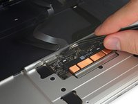
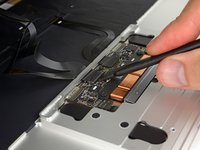
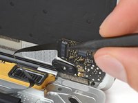
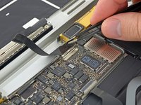
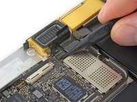
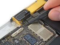
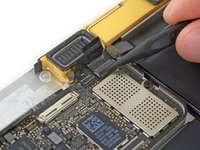
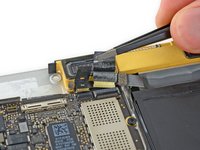
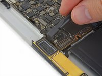
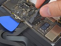
Use a spudger to flip open the retaining flap on the audio jack board cable ZIF connector.
-
-
-
Disconnect the audio jack board ribbon cable by pulling it straight back out of the ZIF connector.
-
-
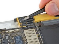
crwdns2935267:0crwdne2935267:0Tweezers$4.99
-
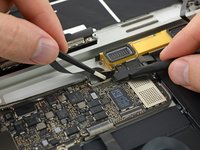
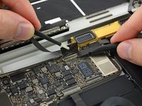
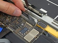
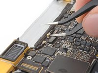
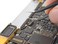
Use tweezers to peel back the tape covering the display cable connector.
-
-
-
If so, use the flat end of a spudger to hold down the retaining flap while peeling the tape away with the tweezers.
-
-
-
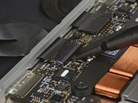
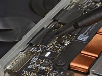
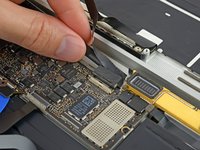
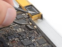
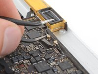
Use the flat end of a spudger to flip open the retaining flap on the display cable connector.
-
Try to keep it clear of the tape, or it may re-adhere and make cable removal difficult.
-
-
crwdns2935267:0crwdne2935267:0iOpener$14.99
-
Carefully slide the flat end of a spudger underneath the display cable to separate the adhesive holding it to the lower case.
-
-
-
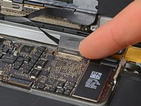
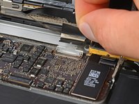
Hold the retaining flap open.
-
Disconnect the display cable by gently pulling it straight out of its connector.
-
-
-
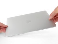
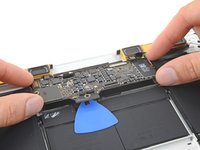
Separate the upper case assembly from the lower case assembly.
-
-
crwdns2935267:0crwdne2935267:0Tweezers$4.99
-
Use tweezers to peel up the tape covering the two ZIF connectors—one for the right speaker cable, and one for the audio jack board cable.
-
-
-
Use the point of a spudger to flip up both ZIF connector retaining flaps.
-
-
-
Carefully pull straight back on the two pieces of tape you just peeled up to disconnect the two ribbon cables.
-
-
-
Use the point of a spudger to peel up the foam pad covering the two antenna connectors.
-
-
-
Insert one arm of your angled tweezers under the metal neck of the first antenna connector and pry up to disconnect it.
-
-
-
Pry up the second antenna connector to disconnect it.
-
-
-
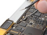
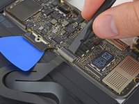
Use a spudger to disconnect the left speaker cable connector by prying it straight up from the logic board.
-
-
-
Use a spudger to flip up the retaining flap on the trackpad cable ZIF connector.
-
-
-
Disconnect the trackpad cable from the logic board by gently pulling it straight out of its connector.
-
-
-
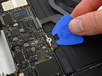
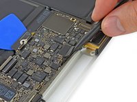
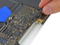
Remove the single 3.5 mm T5 Torx screw securing the logic board to the lower case.
-
-
-
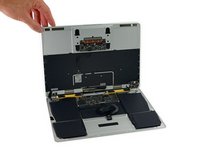
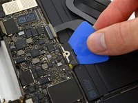
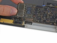
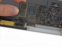
Flip up the front edge of the logic board.
-
Lift and detach the EMI tape securing the logic board to the lower case.
-


To reassemble your device, follow these instructions in reverse order.
To reassemble your device, follow these instructions in reverse order.
crwdns2935221:0crwdne2935221:0
crwdns2935229:021crwdne2935229:0

crwdns2947412:07crwdne2947412:0
Following this guide for repair will likely kill your MacBook… just saying.
Best to visit an Apple Authorised Service Provider.
How so? Enlighten us if you would be so kind good sir...
Hortman -
Because this is a Logic Board replacement guide, if I had to guess… I’d say their MacBook is already “dead.” 😉
Are you suggesting that they will damage their newly purchased Logic Board during installation? It’s not unheard of.
Well, hence my MacBook Pro is dead, and a repair would cost about 800€, I think I’ll try. If it fails, I just buy a used one for about the same money.
The easiest error to make when working on this motherboard if applying full voltage after re-assembly. According to the big A, the motherboard on these Macbooks need to be “woken up” with a 5 watt (phone size) charger. Applying the normal 29 watts may render your system unusable.