crwdns2915892:0crwdne2915892:0
In this guide, you will learn how to remove the motherboard from your Asus M570D. This repair is necessary if the motherboard is defective or if you want to replace other components located deep inside the device.
crwdns2942213:0crwdne2942213:0
-
-
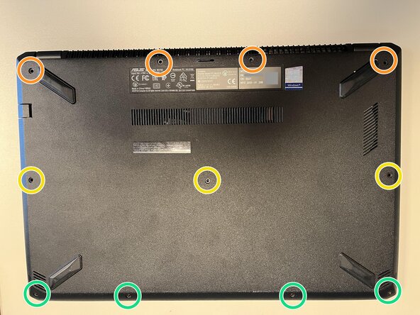
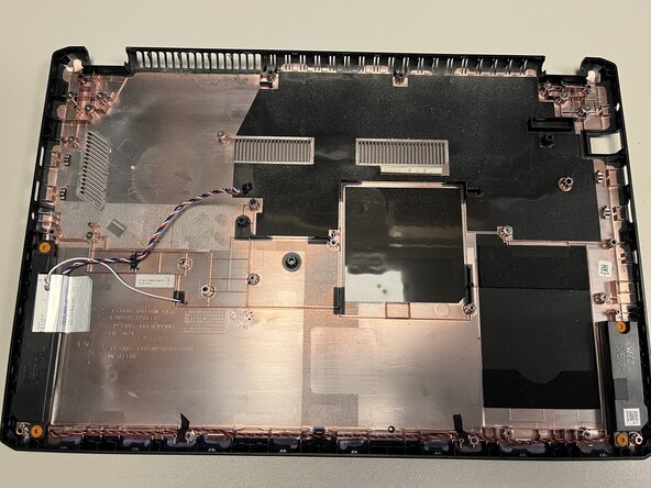
Close the laptop, place it on its lid, and align it as shown in the image
-
There are three different screw lengths:
-
4 x PH1 12 mm (orange)
-
3 x PH1 10 mm (yellow)
-
4 x PH1 7 mm (green)
-
The screws must be reinstalled in the correct position later, otherwise something can be damaged.
-
Take out the screws and sort them by length.
-
-
-
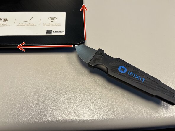
Turn the device over and open it.
-
Carefully insert the Jimmy into the gap between the case and the keyboard at the lower right corner of the keyboard.
-
From this position, work your way forward by levering alternately to the left and up until the keyboard is loose on the case.
-
-
-
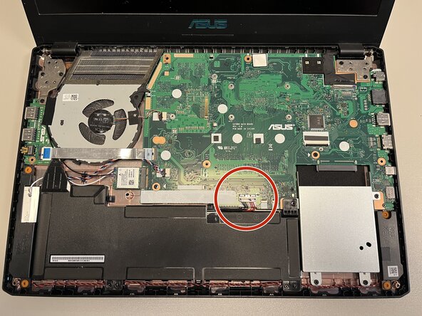
There are 4 cables that must be removed!
-
Carefully open the keyboard under the touchpad, move it in the direction of the screen.
-
Use the spudger to lift the black lock on the ribbon cable and carefully pull out the cable. Repeat this for each one of the four ribbon cables.
-
-
-
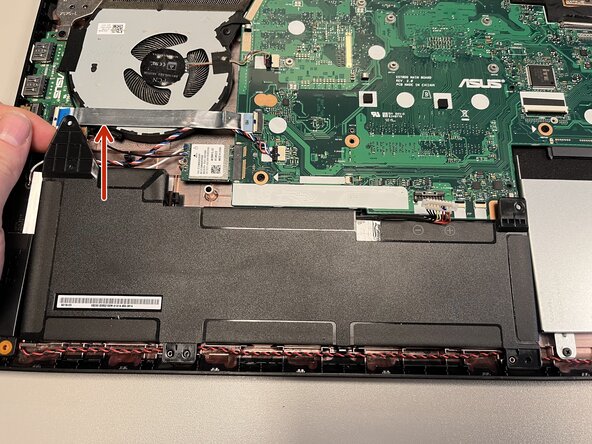
Locate the battery connector.
-
Carefully slide the metal clip (marked blue in the picture) upwards to unlock the connector.
-
Use the spudger to lift the white connector upwards.
-
-
-
Remove the two screws (PH1 - 8 mm)
-
-
-
Remove the battery by lifting it upwards.
-
-
-
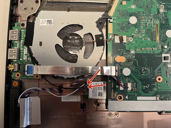
Carefully disconnect the two antenna cables using tweezers.
-
-
-
-
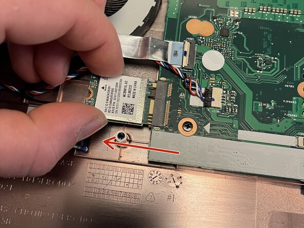
Carefully pull the Wi-Fi card out to the left.
-
-
-
Flip up the black lock on the socket.
-
Pull the cable out to the left
-
-
-
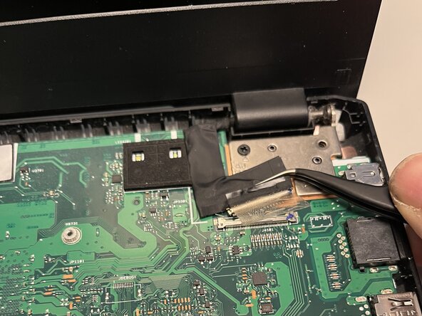
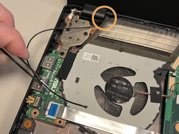
Use tweezers to carefully remove the adhesive tape over the display cable connector.
-
Pull the connector upwards out of the socket.
-
Carefully detach the entire cable from the circuit board.
-
-
-
Carefully thread out the antenna cable using tweezers.
-
-
-
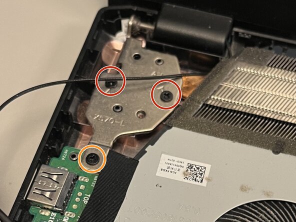
Remove the screw marked in orange. (PH1 8 mm)
-
Remove the screws marked in red (2 pcs. PH1 6 mm)
-
-
-
Remove the screws (2 x PH1 - 6 mm)
-
Set the display assembly aside.
-
-
-
Here you can see the removed display assembly for reference.
-
-
-
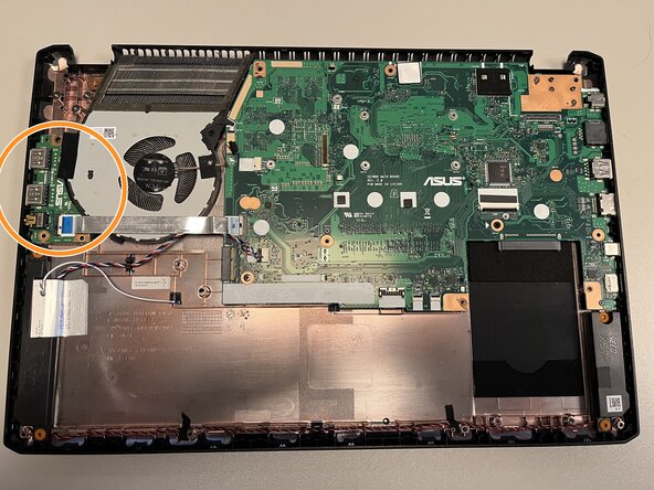
Carefully lift the I/O board and release it from its holder. Take care not to damage any adjacent cables or components.
-
-
-
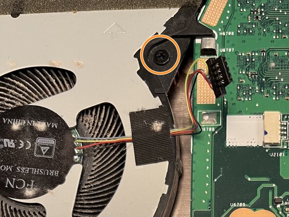
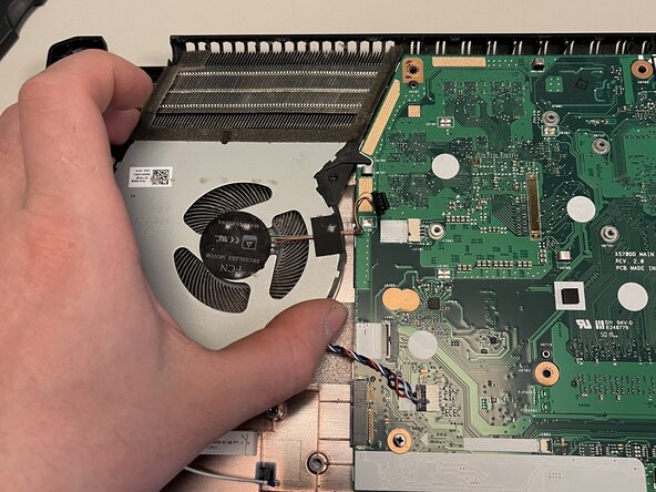
Carefully pull the fan cable toward the left side of the device.
-
-
-
Remove the screw (PH1 - 5 mm)
-
-
-
Lift out the fan.
-
You can clean it at the same time.
-
-
-
Pull the speaker cable out to the left.
-
-
-
Remove the two screws. (PH1 - 5.5 mm)
-
-
-
Carefully lift the motherboard and pull it slightly to the left to release it from the case.
-


Follow the steps in reverse order to reassemble your device.
Follow the steps in reverse order to reassemble your device.
crwdns2934873:0crwdne2934873:0
100%

crwdns2934883:0oldturkey03crwdne2934883:0 crwdns2934875:0crwdne2934875:0
crwdns2934877:0crwdne2934877:0 ›