crwdns2915892:0crwdne2915892:0
Power bricks are essential to operating our electronic devices. Even manufacturers who are known for their quality products are guilty of producing power bricks that quickly go bad. You could simply pay a premium price to buy a new replacement power brick from the device maker, but it is usually fairly simple to repair the existing power brick to be as good as new. These instructions are fairly general, but I will use as an example the power brick for some Bose Companion 20 speakers. This power brick is labeled as BOSE model PSM36W-180. The procedure for Apple laptop power bricks is very similar.
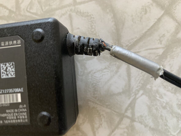
Most power bricks fail in the same way. The insulation starts to disintegrate near where the DC output cord exits the power brick, leaving bare wires exposed. Now you have a safety hazard that could lead to a short circuit.
You could try to cover this up with electrical tape, but the bad spot might persist underneath the tape or inside the plastic stress relief stub where the cord exits the power brick. I will show you how you can remove the bad part of the cord, leaving the remaining cord as good as new.
crwdns2942213:0crwdne2942213:0
-
-
Before investing much time in this project, make sure that the power brick is still working. The easiest way is to plug it in, turn on the device, and see if it seems to work okay.
-
If you have a voltmeter, a better test would be to confirm that the power brick is producing the correct output voltage. Usually there's a label on the power brick identifying the output voltage and polarity. In this case, my power brick produces 18 volts, and the plug is wired with positive lead connected to the center conductor.
-
To test the output voltage, put the red lead of your voltmeter into the inside the central hole of the cylindrical connector that plugs into your device. Attach the black lead to the shiny metal of the exterior of the same cylindrical connector. Confirm that the output is 18 volts.
-
If the power brick isn't producing any output, try jiggling the wires to get measurable output. If the power brick still isn't producing any output, it might be toast. Then again, it still might be worth your while to proceed to the next step.
-
-
-
This is the trickiest step of the procedure. You want to crack open the power brick's plastic case along the existing seam, without cosmetically ruining it. Ideally, nobody will be able to tell that you opened up the case but--even if you are very careful--in most cases you will leave behind some minor scars on the plastic.
-
Sometimes you get lucky and the power brick case is held together by screws. Sometimes these screws are hidden underneath printed labels. If there are labels on the power brick, press your fingertips against the label, feeling for small screw holes hidden underneath.
-
If you discover screw holes, either peel back the label or else punch through the label to reveal the holes. You have to decide which is cosmetically better. Then use the appropriate screwdriver to remove all screws. Take careful note of which screw comes out of which hole, in case some are longer than the others.
-
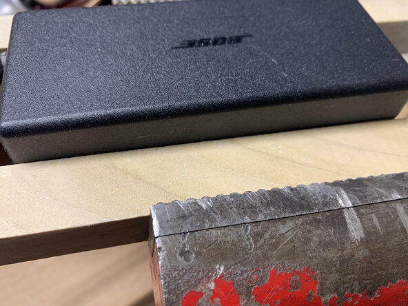
More likely, the power brick is glued together, as is the case with the pictured Bose power brick. To carefully break this glued joint: Using wood blocks to avoid marring the plastic, place the unit into a bench vise and tighten until you hear light popping sounds of the glued joint giving way. Note how the case seam bulges upwards (first photo).
-
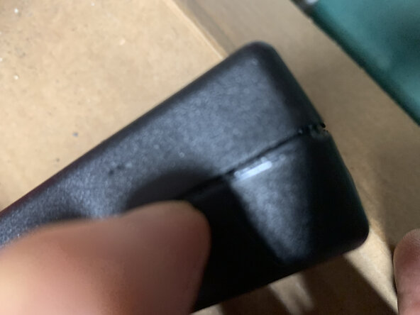
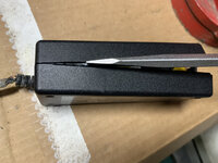
With the vise, alternately squeeze the upper and lower halves of the case in different places and different directions (second photo). Try squeezing at the corners, along the end, and just in the middle of the case. Eventually the seam will split open enough for you to pry the case open with your nails (third photo).
-
-
-
-
Cracking the case open was the hardest step, but you can still mess up if you aren't careful. Next you need to carefully separate the two case halves. Sometimes you can pry with a large screwdriver, taking care not to scar the plastic. In other cases, keep flexing the case inside the bench vise until you can separate the halves by hand.
-
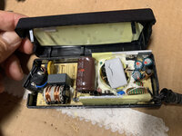
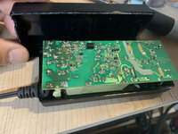
Note carefully the orientation of the circuit board inside the case. In this case the circuit board only fits in one orientation, but in others it might not be clear. Take photos as you go along, to help with later reassembly.
-
The circuit board simply lifts out of the case. In other designs you may need to pop some plastic latches or remove some screws to free the circuit board.
-
-
-
This is the second most tricky step. You need to pull the DC cord out of the stress relief collar (where it is glued in), then enlarge the hole enough so you can cut off the damaged part of the cord and push the remaining part of the cord back through the collar. You'll end up sacrificing just a few inches of the DC cable.
-
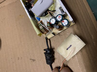
Cut off the DC power cord where it attaches to the printed circuit board. Note carefully that one location is marked +V, while the other is unmarked is ground (Figure 1).
-
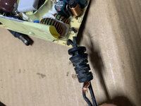
Pull the remaining cord out of the stress relief collar. It appears to be glued in there, so you'll likely end up with a long length of stripped wires. A bunch of black wire insulation remains inside the stress relief collar.
-
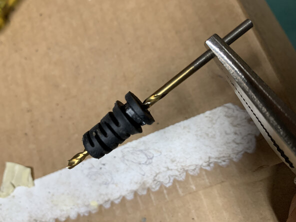
Using a small diameter drill bit, ream out the hole through the middle of the stress relief collar, so it is large enough to pass the DC cord back through it (Figure 2). A bunch of black wire insulation should come out. It may help to progress through several sizes of drill bits, from tiny upto small.
-
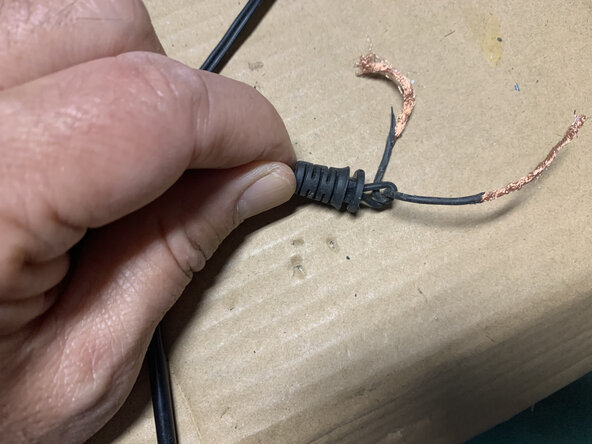
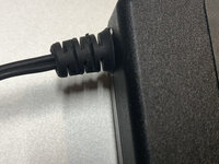
Push the DC power cord through the stress relief collar, starting at the pointy end. Use something stiff, thin and pointy to push it through such as a paper clip. When you are done, pull through about one inch of insulated wire. Tie a knot so the DC power cord can't slip back through the stress relief collar (Figure 3).
-
-
-
Figure out which of the two wires is connected to the center connector on the DC power plug. Insert this through the PC board hole labeled V+. To make sure, put your multimeter into continuity mode, put one probe into the center of the DC power plug, and touch each of the two leads at the other end. The one that beeps goes to V+.
-
The other wire from the DC power cord goes through the PC board hole for the unlabeled negative power terminal. You might need a solder sucker to open up the PC board holes before you can insert the wires.
-
If you're like me, you want to use your multimeter again, to confirm that the center (positive) part of the DC power plug connects to the hole on the PC board labeled V+. Then solder the two wires securely to the PC board.
-
-
-
You may wish to (carefully) test it prior to closing everything up. Just carefully plug it in to the device and to the AC outlet (smoke test), and see if your device operates as expected. If it does, continue with the reassembly. If not, open things up and troubleshoot.
-
Orient the PC board back into the case. The component side of the PC board should be facing the yellow pad. The stress relief collar goes into the small hole at one end of the case. The AC cord socket goes on the end with the large rectangular hole.
-
Once you are confident that things are oriented correctly and working properly, you may glue the plastic power brick case closed. If you promise to be careful, you can instead hold the power brick case closed with tape or some sturdy rubber bands.
-
We're done!
-


You fixed your power brick's DC output cable, by cutting off the bad part, pulling a couple of inches of wire through the stress relief device, and soldering the wires back to the printed circuit board. The procedure is fairly easy, once you are able to crack open the power brick's shell.
You fixed your power brick's DC output cable, by cutting off the bad part, pulling a couple of inches of wire through the stress relief device, and soldering the wires back to the printed circuit board. The procedure is fairly easy, once you are able to crack open the power brick's shell.
crwdns2935221:0crwdne2935221:0
crwdns2935227:0crwdne2935227:0
