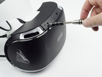
crwdns2915892:0crwdne2915892:0
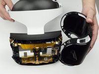
If your PlayStation VR Headset is experiencing location and movement difficulty, use this guide to remove and replace Infrared Range Finder found in the VR headset. Replacing a faulty Infrared Range Finder can greatly improve usability. Please confirm sensor part number prior to purchasing replacement components, since they may vary. The part number should be printed on the sensor itself. It may be necessary to contact Sony for parts, as this sensor is difficult to find.
A troubleshooting guide is also available from Sony here. Please keep in mind that this method requires experience with soldering components directly to a circuit board. If this method is not what you’re looking for, it is also possible to replace the entire sensor board seen in step 25. Remember, computer components are fragile. Be careful with clips and wiring when disassembling and reassembling the computer. They can easily break or get pinched. It may also be helpful to take a picture of wiring routing and component placement before disassembly as a reference for reassembly.
crwdns2942213:0crwdne2942213:0
-
-
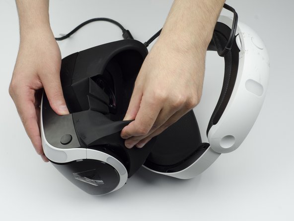
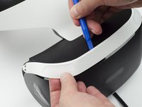
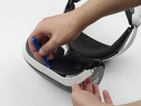
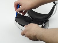
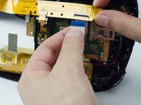
Peel back the rubber covering around the lenses to remove the surrounding plastic eyepieces.
-
-
-
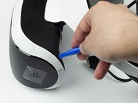
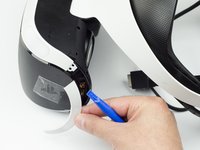
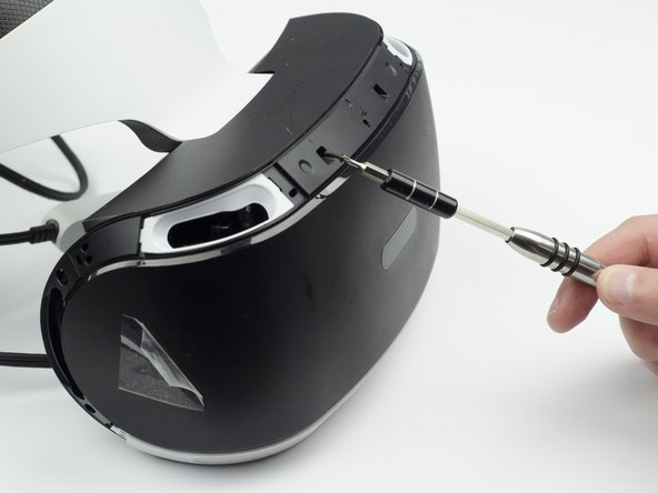
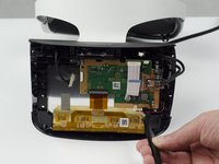
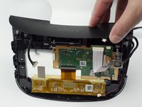
Unscrew four 13 mm screws with a PH #000 screwdriver.
-
-
-
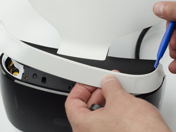
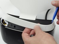
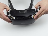
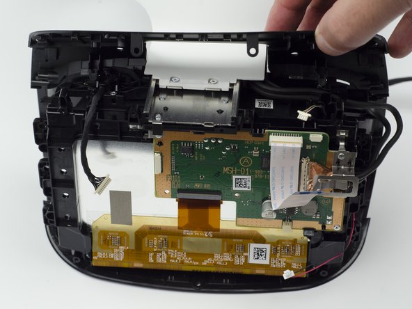
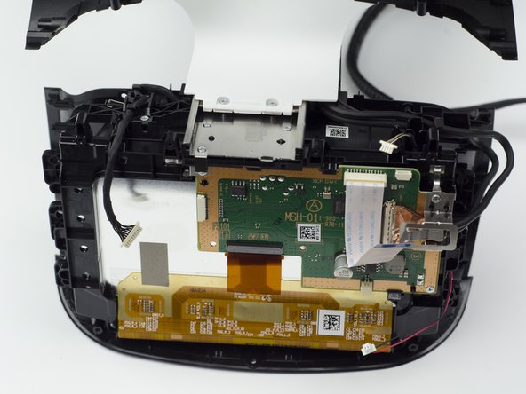
Using the plastic opening tool, carefully pry the white plastic panel free from the side of the headset. Repeat this action for the opposite side.
-
-
-
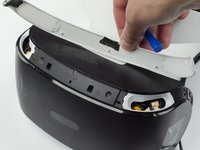
Use the plastic opening tool to pry the top white plastic panel free from the headset.
-
-
-
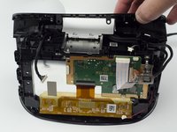
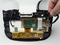
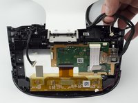
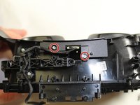
Flip the headset over.
-
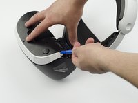
Using a PH #000, unscrew the 7 mm screw found on the bottom of the headset.
-
-
-
Using the plastic opening tool, pry the bottom white plastic panel loose and remove it from the headset.
-
-
-
Unscrew the two 7 mm screws from the top of the headset.
-
-
-
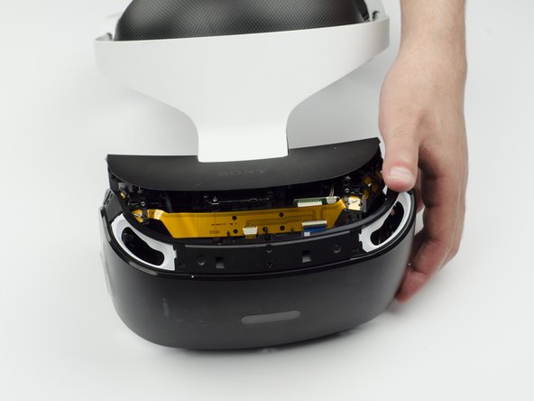
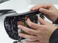
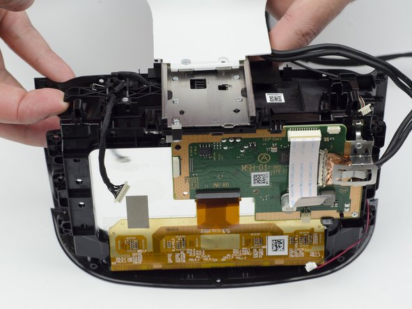
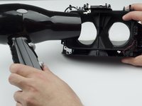
Using your fingers, carefully pry the black front panel free from the headset.
-
-
-
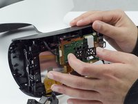
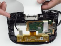
Unscrew the four silver 6 mm screws in each corner using a PH #000 screwdriver.
-
-
-
-
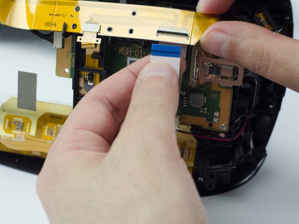
Lift the small silver latch attaching the ZIF (zero insertion force) connector to the circuit board.
-
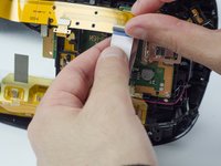
Carefully pull the end of the white ribbon connector from its slot.
-
-
-
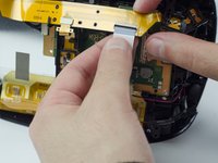
Unhitch the yellow led connector ribbon and move it aside.
-
-
-
Carefully pry the black plastic piece attaching the yellow ribbon to the headset away from the green circuit board.
-
Remove the yellow LED ribbons and black plastic connecting piece from the headset.
-
-
crwdns2935267:0crwdne2935267:0Tweezers$4.99
-
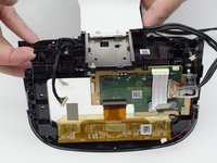
Using the tweezers, unplug the three (one black bundled, two multi colored bundled) connector cables from their ports along the circuit board.
-
-
-
Flip the headset over.
-
Unscrew the two 7 mm screws near the lenses with a PH #000 screwdriver.
-
-
-
Flip the headset back over.
-
With your fingers, carefully pry the top black plastic panel free.
-
-
-
Unscrew one silver 4 mm screw from the white plastic band connecting the rest of the headset.
-
One 4 mm screw with a PH #000 screwdriver.
-
-
-
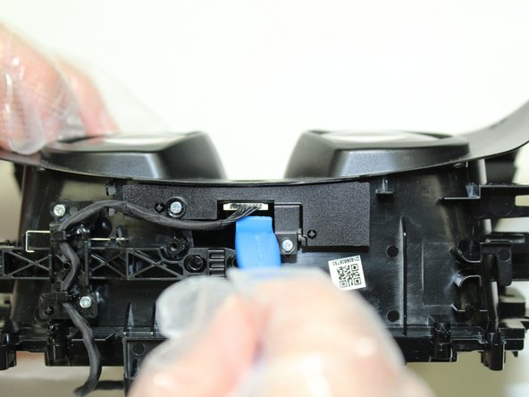
Using a finger, press the black plastic tab up to loosen the white connector piece.
-
Slide the white plastic connector piece back and lift up to remove it.
-
-
-
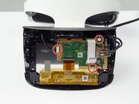
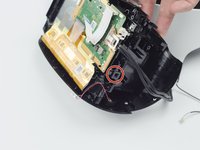
Unscrew the five silver 6 mm screws from the circuit board.
-
Five 6 mm scews with a PH #000 screwdriver.
-
-
-
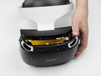
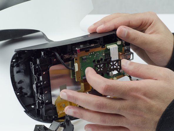
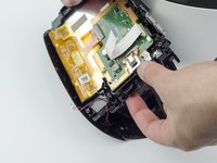
Using your fingers, lift up on the sides of the black plastic piece holding the circuit board in place.
-
There are small plastic tabs on the side that latch the piece in place that need to be lifted in order to remove it.
-
-
-
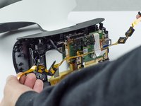
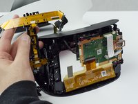
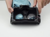
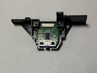
Carefully lift the circuit board out of the headset and set aside.
-
-
-
Using a hairdryer (or heatlamp), warm the area around the lenses. This will help loosen them for removal.
-
-
-
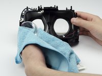
Using a glass cloth (or any cloth with soft fibers), carefully press on the lenses until they pop out of place.
-
-
-
Remove two silver 4mm screws from the bracket assembly containing IMU/infrared range finder board using a Phillips #00 screwdriver.
-
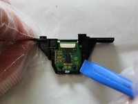
Use an opening tool to pry the connecter from the board.
-
-
-
Gently pry outward with an opening tool to remove the board from the bracket assembly.
-
-
-
Desolder the faulty infrared range finder from the backside of the board.
-


To reassemble your device, follow these instructions in reverse order.
To reassemble your device, follow these instructions in reverse order.

crwdns2915084:0crwdne2915084:0

The Citadel Military College of South Carolina, Team 1-7, Eggleston Fall 2021 crwdns2935289:0The Citadel Military College of South Carolina, Team 1-7, Eggleston Fall 2021crwdne2935289:0
CMCSC-EGGLESTON-F21S1G7
crwdns2931471:03crwdne2931471:0
crwdns2935297:05crwdne2935297:0