crwdns2942213:0crwdne2942213:0
-
crwdns2935201:0crwdne2935201:0 crwdns2935203:0crwdne2935203:0
-
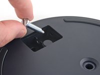
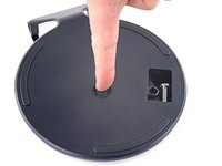
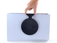
If your PlayStation 5 is in its vertical orientation, flip it upside down so the stand is facing up.
-
Use a coin or a flathead screwdriver to remove the 26.5 mm-long stand screw.
-
-
crwdns2935201:0crwdne2935201:0 crwdns2935203:0crwdne2935203:0
-
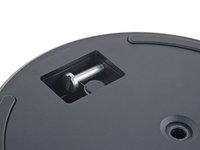
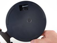
Insert the screw into the cubby on the bottom of the stand.
-
-
crwdns2935201:0crwdne2935201:0 crwdns2935203:0crwdne2935203:0
crwdns2935267:0crwdne2935267:0Tweezers$4.99-
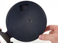
Use a pair of tweezers or your fingernail to remove the cap from the cubby.
-
Use your finger to press the cap into the screw hole.
-
-
crwdns2935201:0crwdne2935201:0 crwdns2935203:0crwdne2935203:0
-
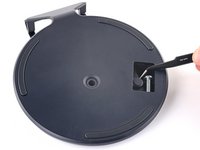
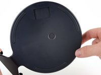
Twist the stand counterclockwise to close the cubby.
-
-
crwdns2935201:0crwdne2935201:0 crwdns2935203:0crwdne2935203:0
-
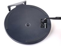
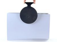
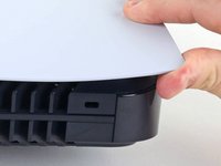
If your PlayStation 5 is in its horizontal orientation, rest it on its face with the charging port facing up.
-
Lift the stand straight up to remove it.
Do you guys sell the stand
Steps 1 through 6 are just about removing the stand, correct? Storing the screw and all that is just about being neat and tidy?
-
-
crwdns2935201:0crwdne2935201:0 crwdns2935203:0crwdne2935203:0
-
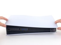
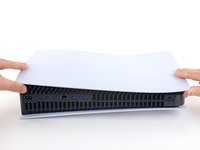
Flip the device over so that the USB and ethernet ports are on the left side from your perspective.
-
Lift up the corner of the faceplate to unclip it from the case.
-
-
crwdns2935201:0crwdne2935201:0 crwdns2935203:0crwdne2935203:0
-
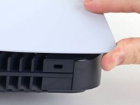
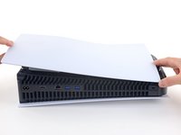
While lifting up the corner, slide the faceplate towards the bottom of the device.
-
Remove the right faceplate.
I recommend doing both covers at this time, to avoid hassle later. Skip to step 38, then come back here
Why remove the other cover? You only need to remove the cover shown in order to access the disc drive.
-
-
crwdns2935201:0crwdne2935201:0 crwdns2935203:0crwdne2935203:0
-
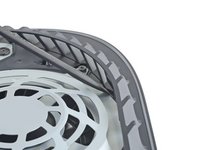
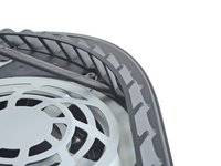
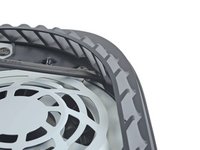
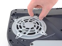
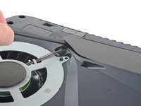
Insert the flat end of a spudger underneath the grille and into the gap above the fan.
-
Lift up with the spudger to pry the grille away from the case.
-
-
crwdns2935201:0crwdne2935201:0 crwdns2935203:0crwdne2935203:0
-
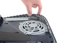
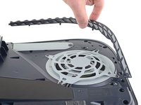
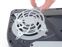
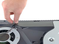
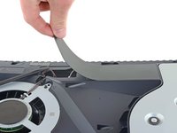
Lift the grille away from the case to remove it.
During reassembling:
There is a little flat pin in each end, they need to go into the console
-
-
crwdns2935201:0crwdne2935201:0 crwdns2935203:0crwdne2935203:0
crwdns2935267:0crwdne2935267:0Magnetic Project Mat$19.95-
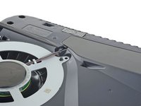
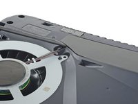
Use a TR8 Torx security driver to remove the four screws securing the fan shroud to the case:
-
Two 23.3 mm-long screws
-
One 11.4 mm-long screw
-
One 31 mm-long screw
My ps5 seems to have tiny black caps over each screw. My spudger can’t get them off I see no other way to move forward besides breaking the shroud
wrong side, take the cover off the other side
The 31 mm-long screw just wont budge! do I turn that one counter-clockwise or clockwise? someone please help!
counter clockwise to remove
I damaged the 23.3mm on the bottom right next to fan connector. Is there any replacements? Can't seem to find any 23.3mm t8 screw anywhere online
I used a t8 for all of them and had no problem removing, except for that bottom right screw
Is there any replacement screws you can buy for the fan? I slightly damage 23.3mm screw.
My PS5 has TX8 (security Torx bit) screws on my fan shroud and all the case screws. A normal Torx driver won’t work you need the one with the hole in the middle of the bit driver.
Why does my ps5 have 3 different screws? 2 are the same then 2 other ones? Why?
Does anyone know the thread pitch of these screws? I just bought a used PS5 and the screws are missing. The fan has been glued in. Can't make this up.....
Ci sono viti di ricambio?
Dove posso trovarle?
Ho guardato dappertutto e non se ne trovano
Sind mit den Massen die dicke oder die Länge gemeint
Thickness I'm sure
9h works also or I HAD a mix up
Thickness I'm sure
-
-
crwdns2935201:0crwdne2935201:0 crwdns2935203:0crwdne2935203:0
-
Lift the fan shroud straight up to remove it.
-
-
crwdns2935201:0crwdne2935201:0 crwdns2935203:0crwdne2935203:0
-
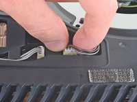
Insert the flat end of a spudger beneath the black wire cover and into the gap above the fan wires.
-
Use the spudger to peel up the wire cover until you can grip it with your fingers.
Some PS5's have a smaller sticky cover instead , remove it in this step
-
-
crwdns2935201:0crwdne2935201:0 crwdns2935203:0crwdne2935203:0
-
Use your fingers to peel off the wire cover.
-
-
crwdns2935201:0crwdne2935201:0 crwdns2935203:0crwdne2935203:0
-
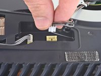
Use your fingers to grip the edges of the fan cable connector, and pull up to disconnect it from the motherboard.
Normally I don't have an issue with this type of connector, but I couldn't get it out with my fingers. I ended up using two plastic pry tools, one on each side of the connector, like a claw game.
So weird you just posted this yesterday. I am doing this right now and your comment helped so much, I couldn’t get mine out at all before I tried that.
-
-
crwdns2935201:0crwdne2935201:0 crwdns2935203:0crwdne2935203:0
-
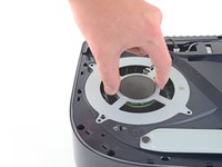
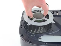
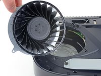
Lift the fan up and out of the case to remove it.
-
-
-
crwdns2935201:0crwdne2935201:0 crwdns2935203:0crwdne2935203:0
-
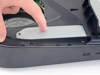
Use a Phillips screwdriver to remove the 17 mm-long SSD cover screw.
-
-
crwdns2935201:0crwdne2935201:0 crwdns2935203:0crwdne2935203:0
-
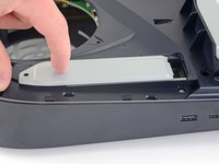
Use your finger to slide the SSD cover towards the top of the device to unclip it from the case.
-
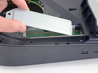
Remove the SSD cover.
It is unnecessary to remove the SSD screw and cover for power supply replacement.
The only thing you can do without removing the ssd cover and screw is remove the fan.
-
-
crwdns2935201:0crwdne2935201:0 crwdns2935203:0crwdne2935203:0
-
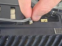
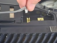
Use your fingers to grip the edges of the optical drive cable connector, and pull up to disconnect it from the motherboard.
For some PS5's, the optical drive connector is still covered in this step. Proceed up to step 22, then you will be able to access these connecters. The connectors will be running across the heatsink visible from step 24.
-
-
crwdns2935201:0crwdne2935201:0 crwdns2935203:0crwdne2935203:0
-
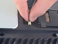
Use your fingers to grip the edges of the optical drive cable connector, and pull up to disconnect it from the optical drive.
-
-
crwdns2935201:0crwdne2935201:0 crwdns2935203:0crwdne2935203:0
crwdns2935267:0crwdne2935267:0Tweezers$4.99-
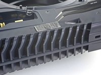
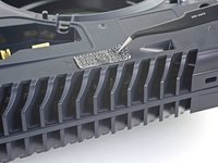
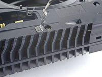
Use a pair of tweezers to remove the tamper-evident sticker covering the remaining case screw.
-
-
crwdns2935201:0crwdne2935201:0 crwdns2935203:0crwdne2935203:0
-
Use a T8 Torx driver to remove the eleven screws securing the case:
-
Six 18.6 mm-long screws
-
Two 23.3 mm-long screws
-
Two 43.2 mm-long screws
-
One 7.3 mm-long screw
-
-
crwdns2935201:0crwdne2935201:0 crwdns2935203:0crwdne2935203:0
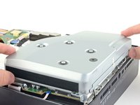
-
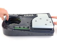
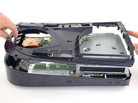
Lift the case straight up to remove it.
-
-
crwdns2935201:0crwdne2935201:0 crwdns2935203:0crwdne2935203:0
-
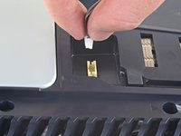
Use the flat end of a spudger to press down on the optical drive connector's metal locking tab.
-
With the metal tab depressed, use a pair of tweezers to pull the blue pull tab directly away from the connector to disconnect the cable from the optical drive.
-
-
crwdns2935201:0crwdne2935201:0 crwdns2935203:0crwdne2935203:0
-
Lift the optical drive away from the device to remove it.
-
-
crwdns2935201:0crwdne2935201:0 crwdns2935203:0crwdne2935203:0
-
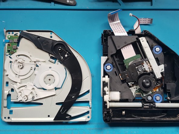
silver screws: 4x M1.6 X 3.7mm, with 6.5mm head.
-
black screws: 9x M1.6 x 3.8mm.
-
Remove screws with Phillips #1 screwdriver.
-
-
crwdns2935201:0crwdne2935201:0 crwdns2935203:0crwdne2935203:0
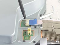
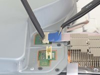
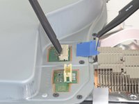
crwdns2935267:0crwdne2935267:0Tweezers$4.99-
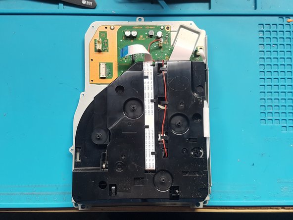
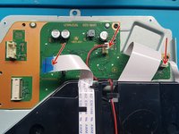
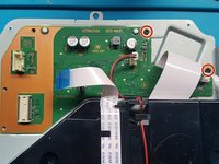
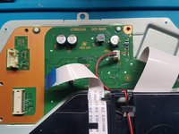
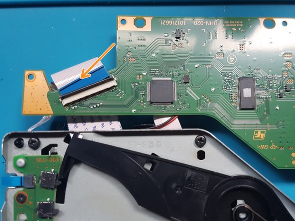
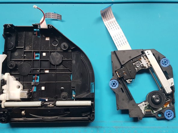
Gently pull the medium and narrow FFC flexes and the 2-wire lead from their sockets. Suitable tweezers (bent with points or straight blunt end) can be used to aid removal.
-
-
crwdns2935201:0crwdne2935201:0 crwdns2935203:0crwdne2935203:0
-
Remove screws with Phillips #1 screwdriver.
-
black screws: 2x M1.6 x 3.8mm
-
-
crwdns2935201:0crwdne2935201:0 crwdns2935203:0crwdne2935203:0
-
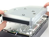
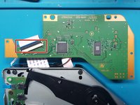
Lift off the PCB and attached assembly from the metal plate.
-
-
crwdns2935201:0crwdne2935201:0 crwdns2935203:0crwdne2935203:0
-
Turn over the PCB and attached assembly.
-
-
crwdns2935201:0crwdne2935201:0 crwdns2935203:0crwdne2935203:0
-
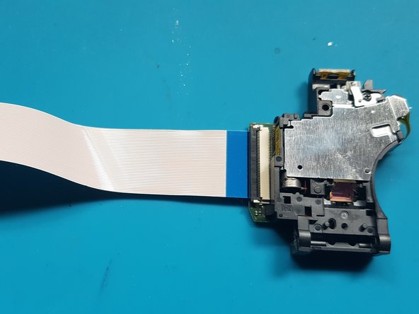
Unlatch the wide FFC socket.
-
Gently remove the wide FFC cable from the socket and set aside the PCB.
-
-
crwdns2935201:0crwdne2935201:0 crwdns2935203:0crwdne2935203:0
-
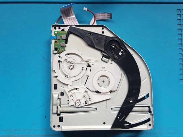
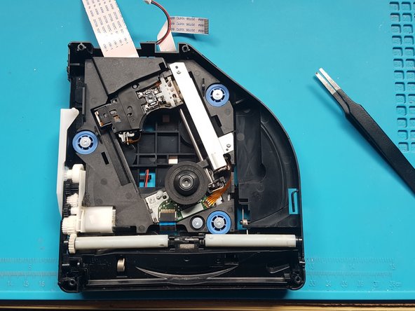
Flip over the assembly.
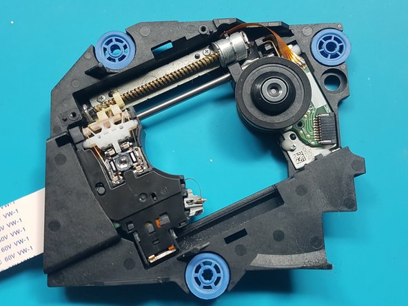
When reassembling be sure the post is engaged in the slot of the upper left dial.
-
-
crwdns2935201:0crwdne2935201:0 crwdns2935203:0crwdne2935203:0
-
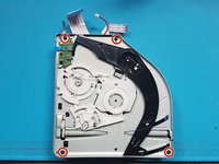
Use a Phillips #1 screwdriver to remove the screws.
-
black screws: 4x M1.6 x 3.8mm.
When reassembling be sure the post is engaged in the slot of the upper left dial.
-
-
crwdns2935201:0crwdne2935201:0 crwdns2935203:0crwdne2935203:0
-
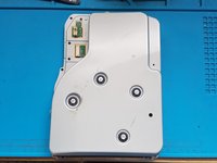
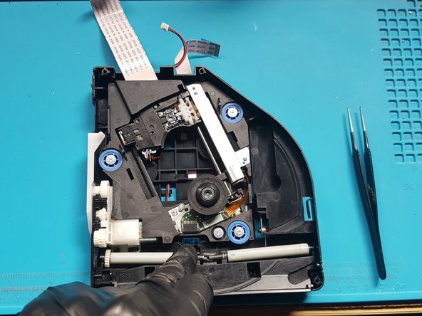
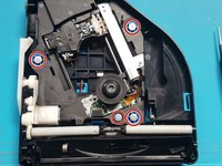
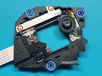
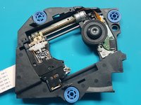
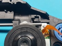
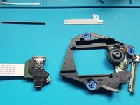
Remove the mechanism plate and set aside.
-
-
crwdns2935201:0crwdne2935201:0 crwdns2935203:0crwdne2935203:0
-
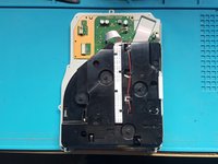
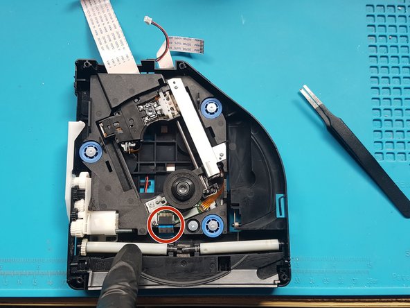
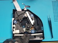
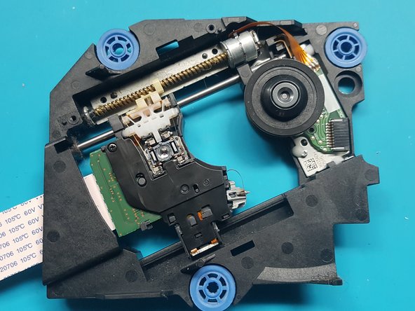
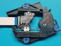
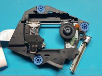
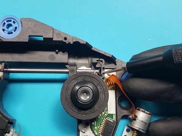
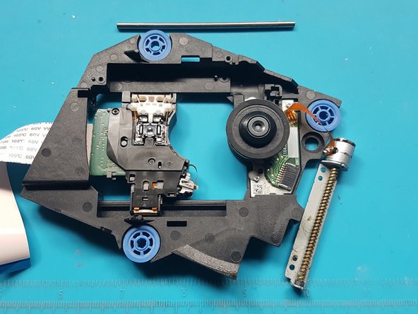
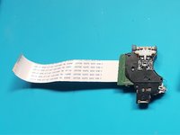
Push down on the roller mech and remove the FFC cable from laser deck (near roller mech).
Found it a lot easier to remove and refit this one after removing the laser deck. Simply unhook from the opposite side and thread through the bottom shell, otherwise it felt like it would end up damaged.
-
-
crwdns2935201:0crwdne2935201:0 crwdns2935203:0crwdne2935203:0
-
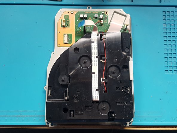
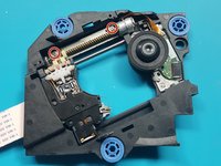
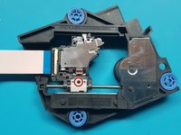
silver screws: 4x M1.6 X 3.7mm 6.5mm head
-
-
crwdns2935201:0crwdne2935201:0 crwdns2935203:0crwdne2935203:0
-
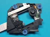
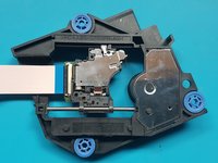
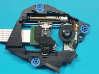
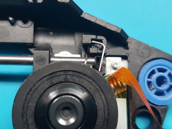
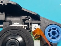
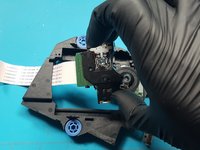
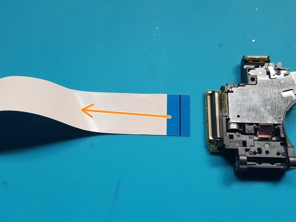
unlatch the FFC connector.
-
Remove the FFC flex from the laser.
Are these generic from a replacement POV or is there some specific model number/code and if shere is it located please? Also do we have to do any resoldering when replacing at all?
TIA
-


crwdns2935221:0crwdne2935221:0
crwdns2935229:010crwdne2935229:0

crwdns2947412:02crwdne2947412:0
Danke für die tolle und ausführliche Anleitung!
Discs werden wieder gelesen *freu*
where do we get the replacement laser?