crwdns2915892:0crwdne2915892:0
Use this guide to replace the plastic rear cover.
crwdns2942213:0crwdne2942213:0
-
-
Use the tip of a spudger to remove the black rubber screw cover from the side of the PS3.
-
-
-
Remove the single 8.5 mm T10 Security Torx screw from the smart plate.
-
-
-
Pull the smart plate toward the hard drive bay, then lift it off the body of the PS3.
-
-
-
Remove the following seven screws:
-
Six 52 mm Phillips screws
-
One 30 mm Phillips screw
-
-
-
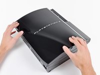
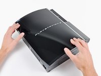
Lift the top cover from its rear edge and rotate it toward the front of the PS3.
-
Remove the top cover.
-
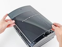
There is a plastic hook located in a hole on the top back right hand side corner. Carefully push the plastic hook a bit from the rear of the machine with a spudger to release the rear right of the casing.
-
-
-
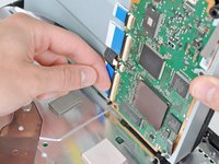
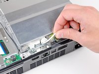
Disconnect the Blu-ray power cable from the motherboard.
-
-
-
-
Lift the Blu-ray drive from the edge nearest the power supply and rotate it away from the chassis enough to access its ribbon cable.
-
-
-
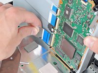
Use your fingernail to flip up the retaining flap on the Blu-ray ribbon cable socket.
-
Pull the ribbon cable out of its socket.
-
Remove the Blu-ray drive from the PS3.
-
-
-
Pull the control board ribbon cable straight up and out of its socket on the motherboard.
-
-
-
Remove the two 12 mm Phillips screws securing the control board to the lower case.
-
Remove the control board and its attached cable from the PS3.
-
-
-
Remove the following eight screws securing the motherboard assembly to the lower case:
-
Seven 12 mm Phillips screws (ph2)
-
One 30 mm Phillips screw
-
-
-
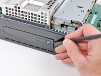
Use the flat end of a spudger to pry the hard drive bay cover away from the lower case.
-
Remove the hard drive bay cover.
-
-
-
Lift the motherboard assembly out of the lower case.
-
-
-
Remove the 7.7 mm Phillips screw securing the ground strap to the chassis.
-
-
-
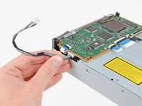
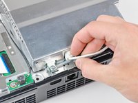
Pull the AC-In cables slightly away from the rear cover for clearance to access the AC-In connector.
-
While depressing its locking mechanism, pull the AC-In connector out of its socket on the power supply.
-
-
-
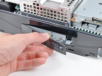
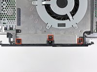
Pull the AC inlet out from the bottom of the rear cover, minding any of its cables that may get caught.
-
-
-
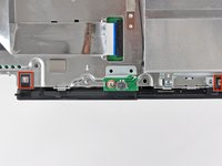
While lightly pulling the rear cover away from the logic board assembly, use the flat end of a spudger to release the clips along the top and bottom edges of the rear cover.
-
-
-
Remove the rear cover from the logic board assembly.
-


To reassemble your device, follow these instructions in reverse order.
crwdns2935221:0crwdne2935221:0
crwdns2935229:09crwdne2935229:0
