crwdns2915892:0crwdne2915892:0
As LCDs age, the segments can bleed and become unreadable. This guide will show you how to replace the entire LCD flex PCB with a functioning part. Removing this part is also necessary for a more complete disassembly of the camera.
crwdns2942213:0crwdne2942213:0
-
-
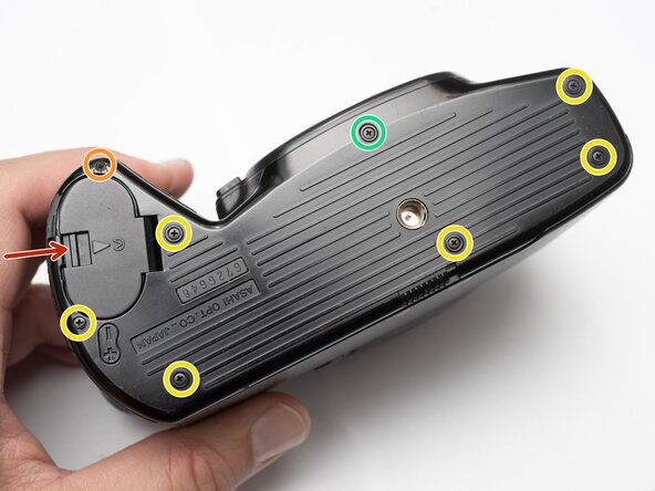
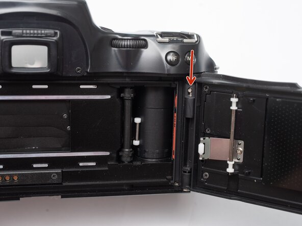
Unlatch battery compartment door.
-
Remove one 1.7 x 4.0 mm screw.
-
Remove six 1.7 x 2.5 mm shoulder screws.
-
Remove one 1.7 x 2.5 mm long shoulder screw.
-
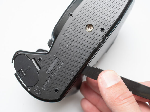
The bottom cover may be adhered with double sided tape in some locations. Use a spudger to gently work it loose.
-
-
-
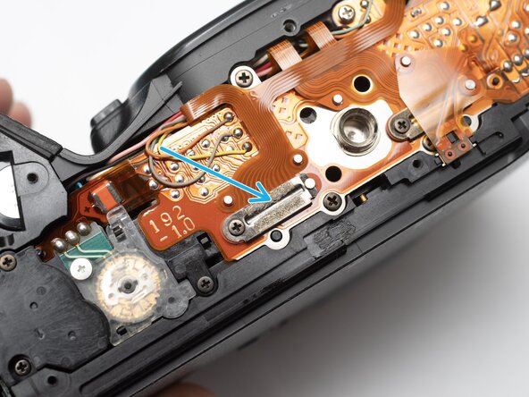
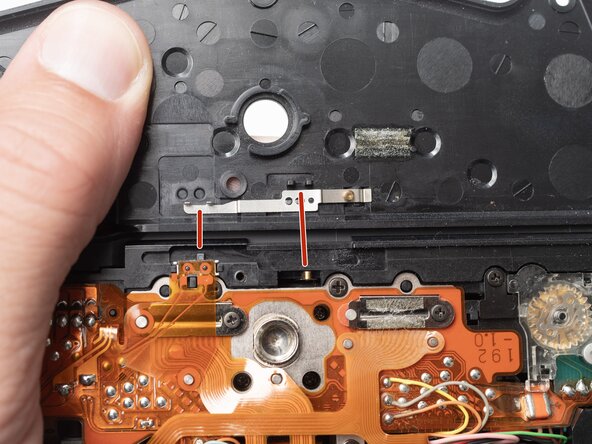
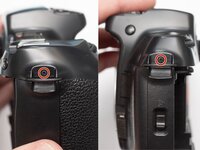
Check that the physical panorama switch on the bottom cover and the electrical switch mate properly.
-
-
-
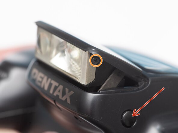
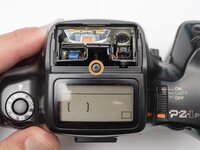
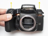
Push button to pop up the flash.
-
Remove two 1.7 x 2.5 mm screws.
-
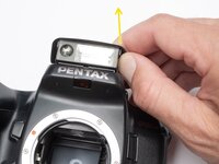
Detach snaps by lifting the side of the flash cover, bending it up and away from the housing.
-
Push flash back down to the stored position.
-
-
-
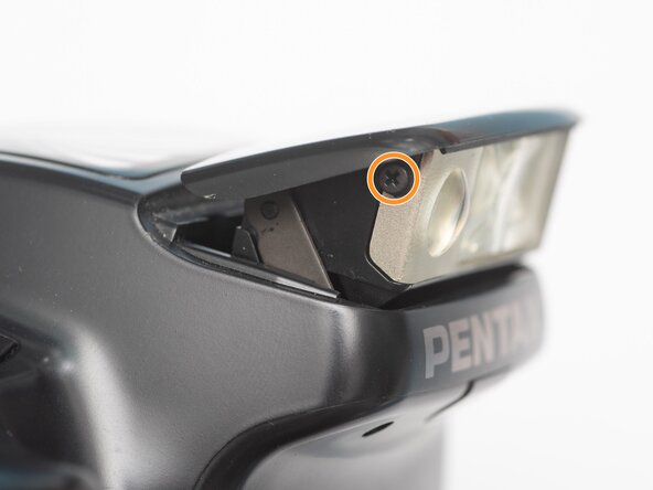
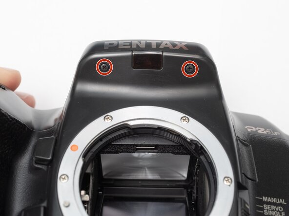
Remove two 1.7 x 2.5 mm screws underneath the pop-up flash.
-
Remove one 1.7 x 2.5 mm panhead screw above the pop-up flash.
-
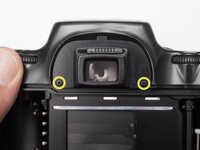
Remove two 1.7 x 2.5 mm shoulder screws near the eye piece.
-
-
-
Remove two 1.7 x 2.5 mm shoulder screws by the strap lugs.
-
Remove one 1.7 x 6.0 mm screw inside the battery compartment.
-
Lift off the top cover.
-
-
-
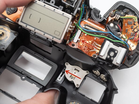
Check that the physical power switch and the electrical power switch are both in the same position before installation.
-
-
-
-
Push the release latch down to remove the film door.
-
-
-
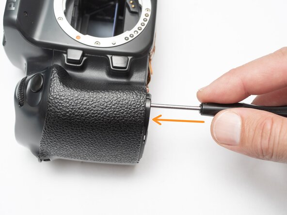
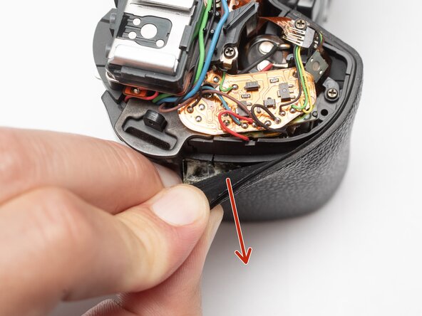
Peel off rubber covering from grip.
-
Remove one 1.7 x 5.0 mm screw.
-
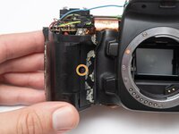
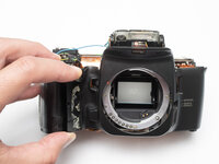
Lift off the front body panel.
-
-
-
Connect a 10 kOhm high power resistor across the terminals of the flash capacitor for several seconds.
-
-
-
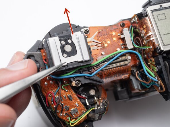
Remove the hot shoe spring. Lift the front of the spring and slide it towards the back of the camera.
-
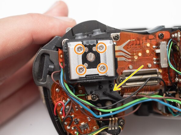
Remove four M1.7 x 6.5 mm screws from the hot shoe.
-
Remove black, brown, green, and blue wires from plastic guides.
-
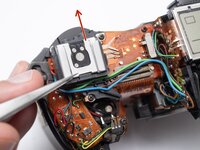
Lift off the hot show mount.
-
-
-
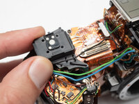
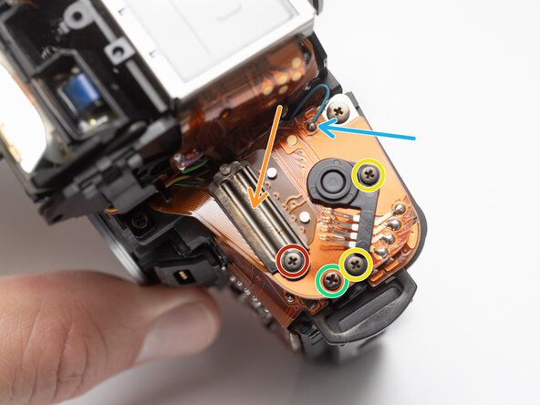
Unsolder the black, green and yellow wires for the command dial contacts.
-
Remove one 1.7 x 4.5 mm screw.
-
Lift off command dial contact.
-
-
-
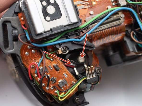
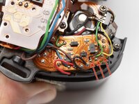
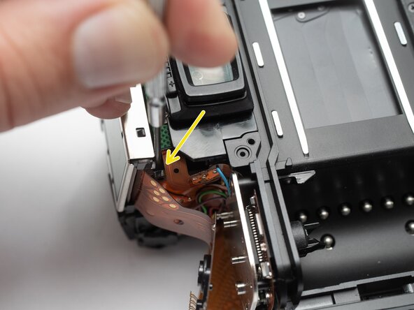
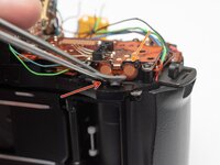
Unsolder the blue and green wires.
-
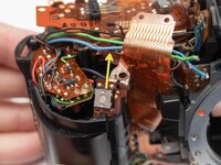
Unsolder the blue, green, brown and black wires from the flash relay PCB.
-
-
-
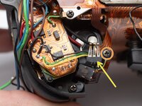
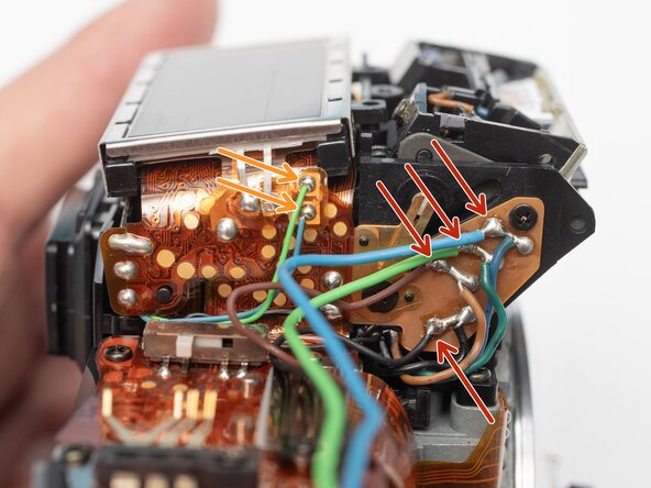
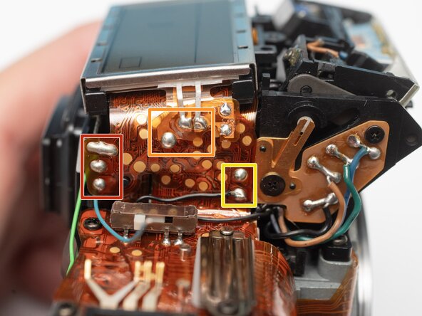
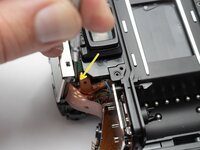
Unsolder three pads.
-
Unsolder three flex connections.
-
Unsolder two through-hole connections.
-
-
-
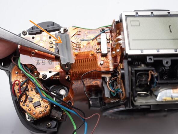
Remove one M1.7 x 2.5 mm screw.
-
Remove flex clamp and rubber pad.
-
Remove one M1.7 x 3.5 mm screw.
-
Remove one 1.7 x 3.5 mm screw.
-
-
-
Remove one M1.7 x 2.5 mm screw.
-
Remove flex clamp and rubber pad.
-
Remove two M1.7 x 2.5 mm screws.
-
Remove one 1.7 x 2.5 mm screw.
-
Unsolder one blue wire.
-
-
-
Remove rubber dome pads for ME an IF buttons.
-
Detach button contacts from housing.
-
Push shutter release button up to free it from its retention post.
-
Detach snaps under the LCD frame.
-
Gently lift off LCD flex PCB.
-


To reassemble your device, follow these instructions in reverse order.