crwdns2915892:0crwdne2915892:0
This guide will tell you how to gain access to and remove the motherboard.
crwdns2942213:0crwdne2942213:0
-
-
Locate the bay door for the battery on the left side of the laptop.
-
-
-
Slide the latch to the right and then down to unlock it.
-
Pull out the battery.
-
-
-
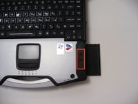
Locate the door for the hard drive on the right side of the laptop
-
-
-
Push and slide the latch up to open the hard drive door.
-
Pull out the hard drive.
-
-
-
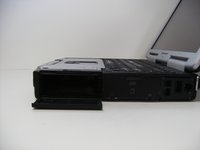
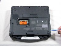
Flip the device upside down with the handle facing away from you.
-
Open the optical drive bay by sliding its latch to the right.
-
Locate optical drive release mechanism on the bottom of the laptop.
-
-
-
Push the exposed switch to the left to eject the optical drive.
-
-
-
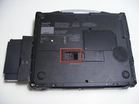
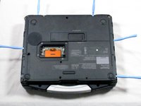
Begin by turning the laptop upside down with the handle towards you.
-
Use a Phillips size 0 screwdriver to remove the 4 screws holding down the ram cover.
-
-
-
-
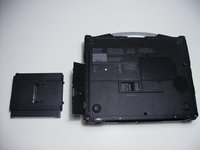
Remove the panel and set it aside.
-
Use a Phillips size 0 screwdriver to remove these 8 small screws.
-
-
-
Use a Phillips size 1 screwdriver to remove the remaining 8 screws.
-
-
-
Use a plastic opening tool to release, but NOT remove, the back cover because it is sealed with adhesive.
-
-
-
Slowly lift the cover so that you can disconnect the red and white wires connecting the speaker to the sound card.
-
-
-
Now the back cover should be off and you can access the inside of the casing.
-
-
-
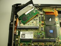
Remove the black and white wires attached to the wireless card by simply pulling up.
-
-
-
Peel back the black cover to expose the clips holding in the wireless card.
-
-
-
Using a pair of plastic opening tools, push the two metal tabs away from the card.
-
-
-
The wireless card should now easily disengage from the motherboard.
-
Pull the card horizontally away from you to remove it from its housing.
-
-
-
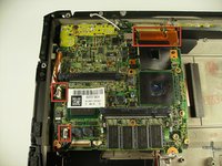
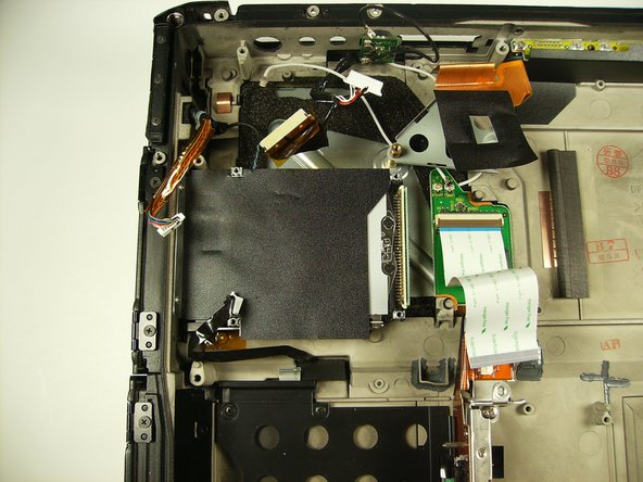
Unplug 3 cables
-
Lift up on brown tab to release cable
-
Pull cable up and out
-
-
-
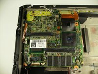
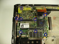
Remove 2 long screws indicated with red circles
-
Remove the remaining screws indicated in blue
I had two more screws to remove in addition to those shown with the blue circles. One in the lower right corner so that you can remove the 14-pin connector that has a metal guard barely wrapped around the edge of the motherboard, the other is on a rectangular copper pad (and has a black arrow by the screwhead) above one of the blue circles near the lower left corner of the large module below the expansion connector.
-
-
-
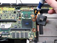
On the back of the unit, unscrew the three screws surrounding the serial port.
-
-
-
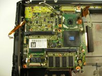
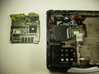
Lift the motherboard as shown, pull towards you and then up.
Between the power connector and the back USB port, there's a post through the motherboard just below the #1 Philips screw you removed previously. The motherboard needs to be lifted off that post to get it out.
-
-
-
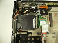
Detach the white ribbon cable, the white cluster connector, and the ribbon cable right next to the cluster
I also had a 2-pin black connector/cable going to the daughterboard that needed to be removed.
-


To reassemble your device, follow these instructions in reverse order.
To reassemble your device, follow these instructions in reverse order.
crwdns2935221:0crwdne2935221:0
crwdns2935229:08crwdne2935229:0
crwdns2915084:0crwdne2915084:0

Cal Poly, Team 27-93, Amido Spring 2010 crwdns2935289:0Cal Poly, Team 27-93, Amido Spring 2010crwdne2935289:0
CPSU-AMIDO-S10S27G93
crwdns2931471:04crwdne2931471:0
crwdns2935297:026crwdne2935297:0
crwdns2947412:04crwdne2947412:0
what about spare parts? is it possible cange MOBO and CPU? in order to upgrade the thoughbook?
I think y'all missed a step.
Où acheter la carte mère?
MERCI
Sur Google, recherchez "DL3UP1396AAA Panasonic CF-29 System Board" (à rechercher sans les guillemets), vous aurez quelques résultats (j'ai vu au moins 2 sites qui la propose à la vente), par contre, elle est cher.
Autre recherche possible : "DL3UP1396BAA Panasonic CF-29 System Board", je ne connais pas la différence entre ces variantes
Autre recherche possible : "DL3U11213FAA Panasonic CF-29 System Board", je ne connais pas la différence entre ces variantes
Brendan -