crwdns2933423:0crwdne2933423:0

Panasonic SDR H-100 Upper Cover Replacement

crwdns2862623:0crwdne2862623:0
crwdns2942641:0crwdne2942641:0

crwdns2942213:0crwdne2942213:0

  1. Panasonic SDR H-100 Upper Cover Replacement, Remove Bottom Screws: crwdns2935265:01crwdnd2935265:01crwdnd2935265:02crwdne2935265:0 Panasonic SDR H-100 Upper Cover Replacement, Remove Bottom Screws: crwdns2935265:01crwdnd2935265:02crwdnd2935265:02crwdne2935265:0
    • Remove the four 4-mm screws on the bottom of the camcorder.

    • The screws are two different colors: three blacks and one silver.

  2. Panasonic SDR H-100 Upper Cover Replacement, Remove Side Screws: crwdns2935265:02crwdnd2935265:01crwdnd2935265:01crwdne2935265:0
    • Remove the three 6-mm screws on the hand-strap side of the camera.

  3. Panasonic SDR H-100 Upper Cover Replacement, Remove DC Input Terminal Screws: crwdns2935265:03crwdnd2935265:01crwdnd2935265:01crwdne2935265:0
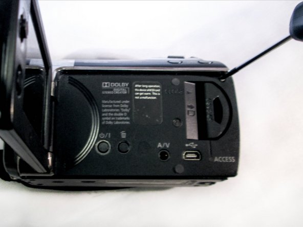
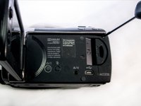
    • Pull out the charging port (DC input terminal) cover and remove the 4-mm screw located next to the input terminal.

  4. Panasonic SDR H-100 Upper Cover Replacement, Remove LCD Monitor Screws: crwdns2935265:04crwdnd2935265:01crwdnd2935265:02crwdne2935265:0 Panasonic SDR H-100 Upper Cover Replacement, Remove LCD Monitor Screws: crwdns2935265:04crwdnd2935265:02crwdnd2935265:02crwdne2935265:0
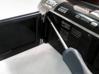
    • Flip out the LCD screen to expose the inner screws. Remove the two black 4-mm screws.

    • One screw is located by the hinge of the LCD screen. The second is close to the upper-right corner of the camcorder body.

    • Using a firm hold on both sides of the camcorder, gently pull apart the casing under the hand strap.

    • Pressure should be evenly distributed across entire device.

    • Detach gently so the ribbon cable is not damaged!

  5. Panasonic SDR H-100 Upper Cover Replacement, Detach Ribbon Cable from Body: crwdns2935265:06crwdnd2935265:01crwdnd2935265:01crwdne2935265:0
    crwdns2935267:0crwdne2935267:0
    Tweezers
    $4.99
    • Use tweezers to grab the ribbon cable at the connection point and slowly lift it away from the connector.

    • This linkage point connects the HDD directly to the motherboard.

crwdns2915888:0crwdne2915888:0

To reassemble your device, follow these instructions in reverse order.

Caleb Osborne

crwdns2935283:004/08/15crwdne2935283:0

837 crwdns2915208:0crwdne2915208:0

crwdns2935297:08crwdne2935297:0

crwdns2915084:0crwdne2915084:0

Eastern Washington University, Team 2-2, Matresse Spring 2015 crwdns2935289:0Eastern Washington University, Team 2-2, Matresse Spring 2015crwdne2935289:0

EWU-MATRESSE-S15S2G2

crwdns2931471:03crwdne2931471:0

crwdns2935297:016crwdne2935297:0

crwdns2947412:00crwdne2947412:0

crwdns2917038:0crwdne2917038:0

crwdns2936625:0crwdne2936625:0:

crwdns2936751:024crwdne2936751:0 0

crwdns2936753:07crwdne2936753:0 0

crwdns2936753:030crwdne2936753:0 1

crwdns2942667:0crwdne2942667:0 63