crwdns2942213:0crwdne2942213:0
-
-
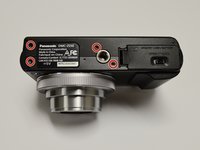
Turn the camera off and identify the battery door located on the bottom of the camera.
-
-
-
Slide the "open" latch to the left: the battery door should spring open.
-
-
-
To release the battery, slide the white release lever next to the SD card slot.
-
-
-
The battery should now be released; you may now remove the battery from the camera body.
-
-
-
Orient the camera so the bottom is facing up and the battery door is on the right side.
-
Remove four black screws from the bottom of the camera.
-
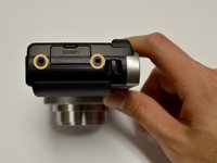
Remove two black screws from the right side of the camera.
-
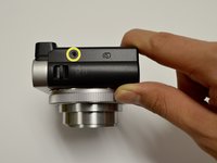
Remove one black screw from the left side of the camera.
Could specify which screws are used, for reassembly. If not the gauge of the screw, maybe at least the color of the screw (black for external, silver for internal?)
-
-
-
-
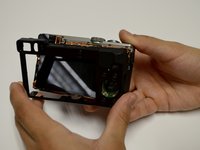
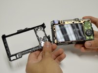
Remove the casing from the camera by hand or using a plastic opening tool.
-
-
-
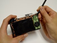
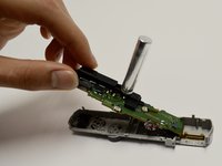
Use a spudger to lift up and tug off the green button board.
-
Be careful to not damage the attached ribbon cable.
-
-
-
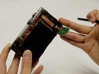
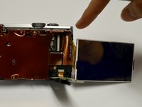
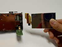
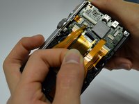
Remove the screen using the plastic opening tool, prying from the top.
-
Once it's lifted up, tug lightly on the large ribbon cable to detach the screen from the camera body.
Was slightly confusing on how to detach/reattach the LCD screen; could possibly use markers or arrows to denote the direction it should be pulled in order to prevent damage to ribbon cables.
-
-
-
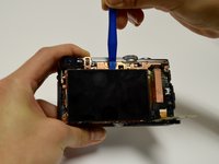
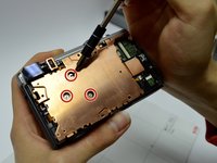
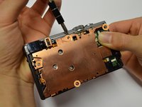
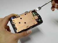
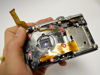
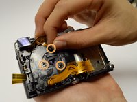
Remove the three screws from the center of the copper plate.
-
Remove the four screws from the outer edges of the copper plate.
-
Use a plastic or metal spudger to pry the copper plate out of place.
May want to consider using a plastic spudger rather than a metal one since metal on metal may scratch, unless the plastic spudger didn't fit.
-
-
-
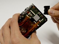
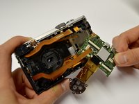
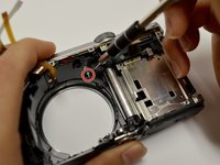
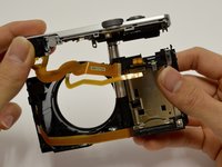
Remove the casing from the circuitboard by hand.
-
Remove the HDMI port casing by hand.
-
-
-
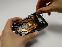
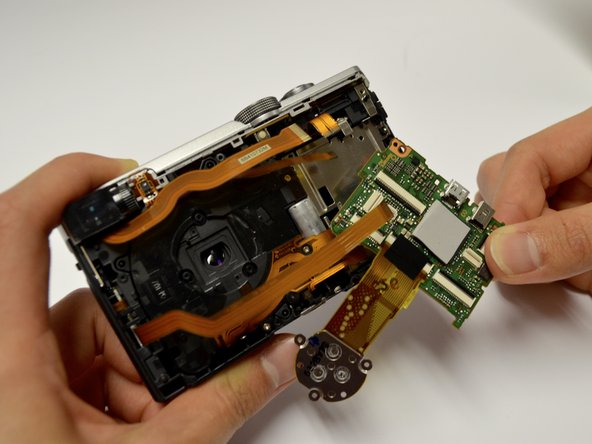
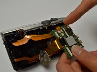
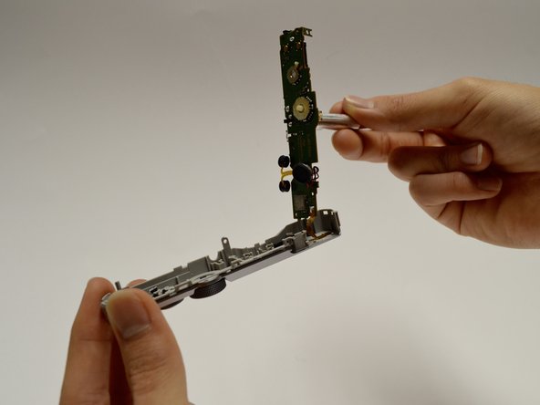
Disconnect all orange ribbon cables connecting to the circuitboard by hand.
-
Disconnect the circuitboard by hand.
-
There will be one orange ribbon cable attached to the top that can now be removed.
-
-
-
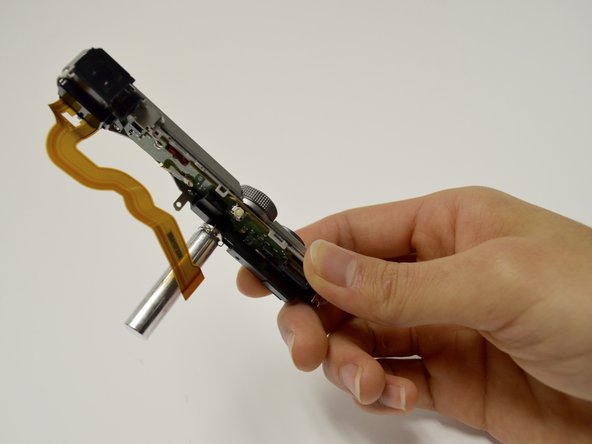
Remove the seven screws surrounding the lens assembly.
-
Remove the three springs surrounding the lens.
-
Apply pressure on the front of the lens to push the lens out.
Removal of the seven screws was unnecessary for disassembly regarding this repair section. The screws provide access to the inside of the lens, which was not involved in component disassembly.
-
-
-
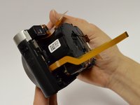
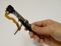
Remove the one screw holding the camera and the flash component together.
-
Gently pull the flash component out of the camera body.
-
-
-
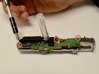
Separate the top camera casing from the flash component by unscrewing the three surrounding screws.
-
Remove the flash assembly, including the circuit board, by detaching it and the ribbon cables from the casing.
-


To reassemble your device, follow these instructions in reverse order.
To reassemble your device, follow these instructions in reverse order.
crwdns2935221:0crwdne2935221:0
crwdns2935227:0crwdne2935227:0
crwdns2915084:0crwdne2915084:0

Baylor, Team 8-5, Whitney Spring 2017 crwdns2935289:0Baylor, Team 8-5, Whitney Spring 2017crwdne2935289:0
BU-WHITNEY-S17S8G5
crwdns2931471:03crwdne2931471:0
crwdns2935297:07crwdne2935297:0
crwdns2947410:01crwdne2947410:0
Step 7: Does not mention the HDMI port door. Make sure you account for it