crwdns2942213:0crwdne2942213:0
-
-
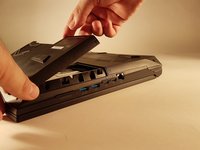
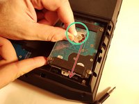
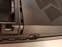
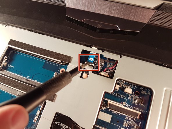
Unlock the lock circled in red.
-
-
-
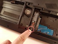
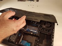
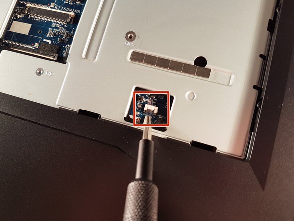
Lift the battery while unlocking the lock circled in red.
-
-
-
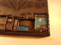
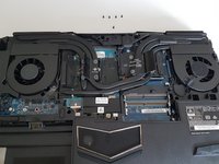
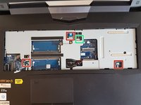
Unscrew the two screws circled in red.
-
Slide the plate in the direction of the arrow.
-
-
-
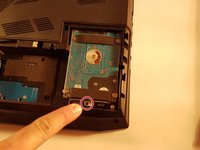
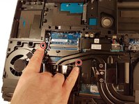
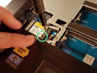
Unscrew the screw circled in red.
-
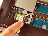
Lift the disk with the green tab.
-
Remove the disk in the direction of the arrow.
-
-
-
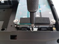
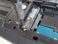
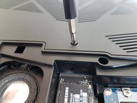
Unscrew the screw circled in red.
-
-
-
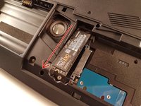
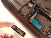
Pull the SSD in the direction of the red arrow.
-
-
-
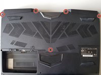
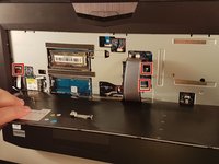
Unscrew the five screws circled in red.
-
-
-
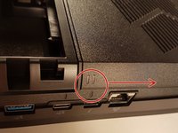
Slide the plate in the direction of the red arrow.
-
-
-
Unscrew the two screws circled in red
-
-
-
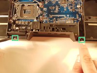
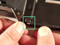
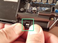
Press a paper clip in the three places marked in red
-
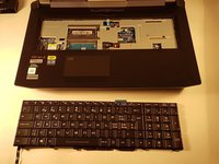
Lift the keyboard and feel free to put some strength
-
-
-
-
Disconnect the three framed connectors in red
-
-
-
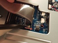
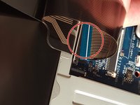
Pull the white drawer in the direction of the arrow to unlock the connector
-
Disconnect the red circled connector
-
-
-
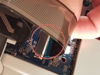
Pull the black drawer in the direction of the arrow to unlock the connector
-
Disconnect the red circled connector
-
-
-
Lift the flap that holds the connector circled in red
-
Disconnect the red circled connector
-
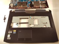
Remove the keyboard
-
-
-
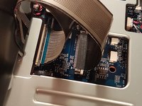
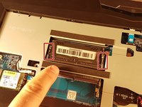
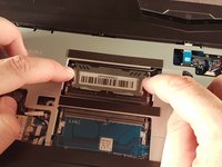
Spread the two clips in red.
-
Remove the RAM card.
-
-
-
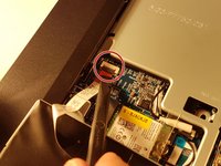
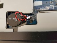
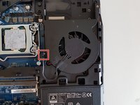
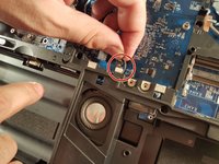
Disconnect the connector circled in red.
-
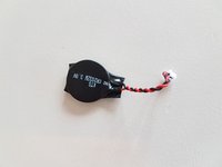
Remove the battery.
-
-
-
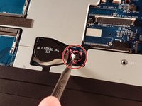
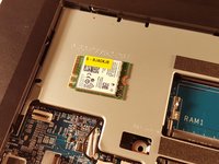
Unscrew the screw circled in red.
-
Disconnect the two connectors circled in green.
-
Remove the WLAN card.
-
-
-
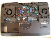
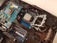
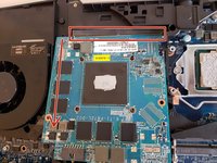
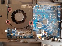
Unscrew the four large screws circled in green
-
Unscrew the five small screws circled in red
-
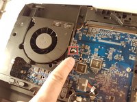
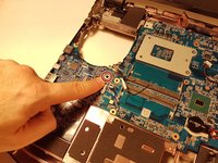
Lift the cooler with the two tabs circled in blue
-
-
-
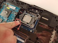
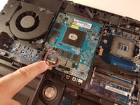
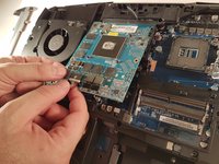
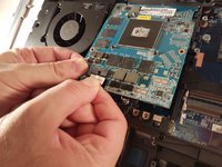
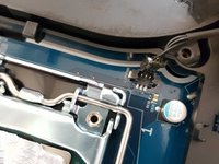
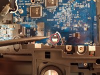
Pull the lever circled in red in the direction of the red arrow while pressing on it.
-
-
-
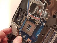
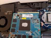
Unscrew the two screws circled in red
-
-
-
Lift the card to allow access to the red circled connector
-
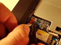
Disconnect the red circled connector
-
-
-
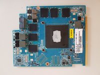
Pull it in the direction of the red arrow
-
-
-
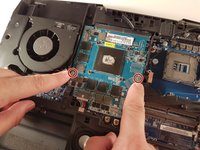
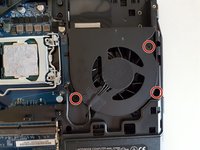
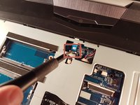
Unscrew the three screws circled in red.
-
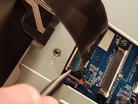
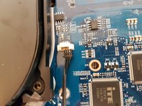
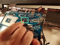
Disconnect the framed connector in red.
-
-
-
Unscrew the three screws circled in red.
-
Disconnect the framed connector in red.
-
-
-
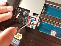
Lift the flap that holds the two connectors framed in red.
-
Disconnect the two framed connectors in red.
-
-
-
Lift the flap that holds the two connectors framed in red.
-
Disconnect the two framed connectors in red.
-
Disconnect the box connector in green.
-
-
-
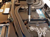
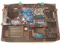
Unscrew the twenty screws circled in red.
-
Unclip the edge of the case at the two places framed in green.
-
-
-
Unclip the edge of the case at the two places framed in green.
-
Remove the top of the case.
-
-
-
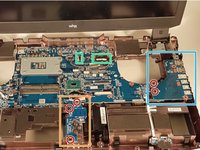
Unscrew the five screws circled in red.
-
Remove the framed card in blue.
-
Remove the framed card in orange.
-
-
-
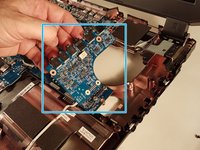
Disconnect the two framed connectors in green.
-
-
-
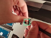
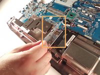
Disconnect the red circled connector.
-
-
-
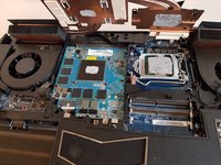
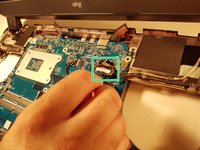
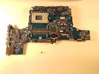
Unscrew the screw circled in red.
-
Remove the motherboard.
-


To reassemble your device, follow the instructions in reverse order.
crwdns2935221:0crwdne2935221:0
crwdns2935229:02crwdne2935229:0
crwdns2934873:0crwdne2934873:0
100%


crwdns2934885:0crwdne2934885:0 crwdns2934875:0crwdne2934875:0
crwdns2934877:0crwdne2934877:0 ›