crwdns2915892:0crwdne2915892:0
Your monitor LCD Screen has stopped working? It may be time to replace it. This guide will walk you through the simple steps to access and replace your monitor.
crwdns2942213:0crwdne2942213:0
-
-
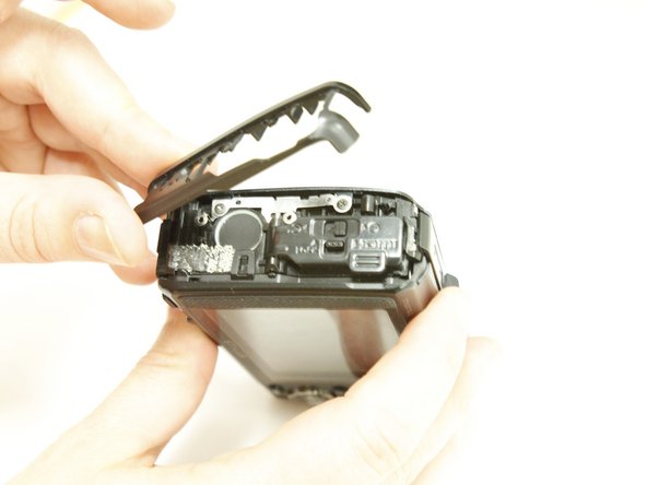
Locate the side of the camera with the connector cover.
-
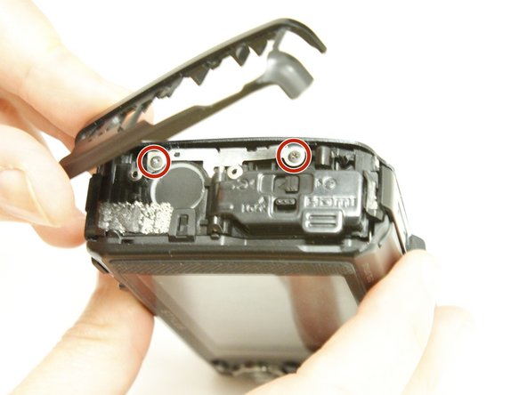
Remove the 2 Phillips #00 4.6mm casing screws.
-
-
-
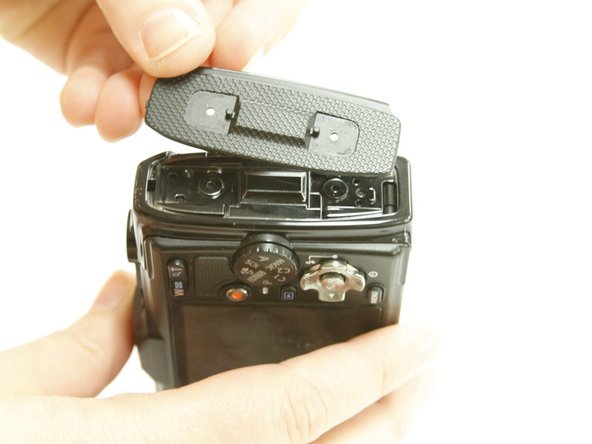
Open the connector cover by sliding the tab labeled lock to revile orange.
-
Slide the connector cover lock to revile orange and the door will spring open.
-
Remove the single internal Phillips #00 3.77mm screw.
-
-
-
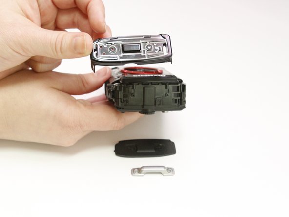
Close the door to gain access to the casing.
-
Use your fingers to remove the black plastic casing that surrounds the connector door.
-
Use your fingers to remove the next black plastic piece .
-
Remove the two screws revealed
-
-
-
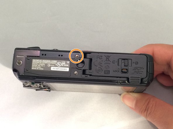
Locate the strap eyelet side of the camera and remove the 2 Phillips #00 5.3mm screws in the handle.
-
Using your fingers, take off the handle, the black casing underneath, and gently wiggle out the shiny black casing below that.
-
-
-
On the bottom of the camera, remove the single Phillips #00 3.5mm screw from the casing below the grip.
-
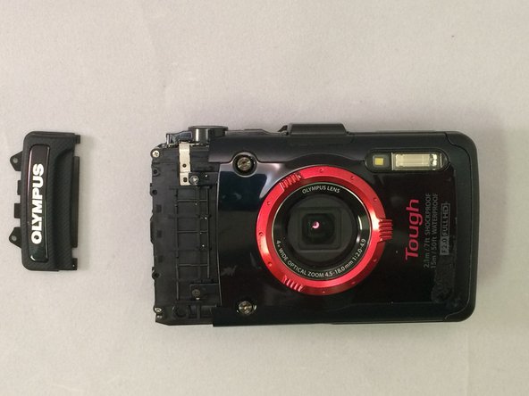
Using a plastic opening tool, gently pry the Olympus grip up and remove it.
-
-
-
-
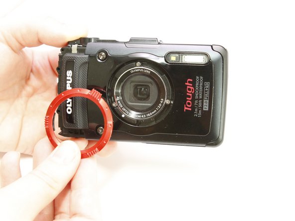
Remove the red ring surrounding the lens by twisting it counter-clockwise
-
-
-
Remove the 2 Phillips #00 3.4mm screws that secure the faceplate just reveled by the grip.
-
On the bottom of the camera, remove the single Phillips #00 3.4mm screw by the tripod socket securing the face plate.
-
-
-
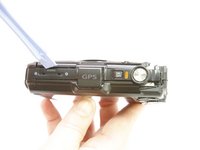
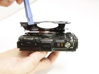
Use a plastic prying tool to lift and remove the faceplate .
-
There will be some resistance from a sticker just under the GPS logo.
-
-
-
To detach the monitor screen, remove the following 7 screws:
-
Locate the flash and remove the 2 Phillips #00 9.23mm & 14.87mm screws.
-
Locate the battery door and remove the single Phillips #00 3.37mm screw.
-
On the bottom of the camera, remove the single Phillips 3.58mm screw near the tripod socket.
-
-
-
On the face plate, locate and remove the 2 eyelet strap side Phillips #00 9.2mm corner screws and the lower battery corner Phillips #00 14.87mm screw.
-
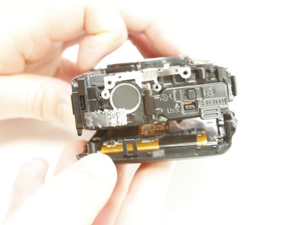
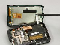
Use your fingers to unclasp the casing clips on either side of the camera and pull down the monitor casing.
-
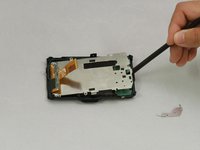
Using the spudger to gently pry the screen away from the body of the camera.
-
-
-
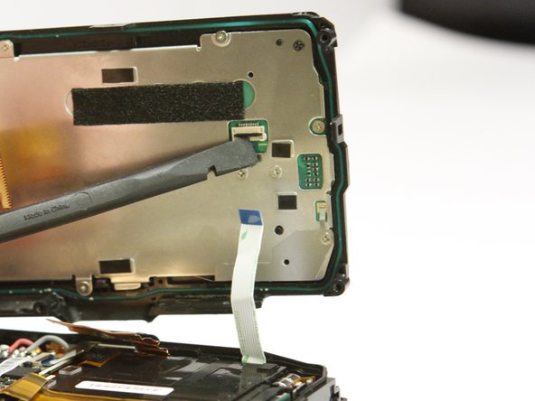
Locate the clasp for the white ribbon.
-
Use the spudger to lift the clasp releasing the ribbon
-
-
-
Locate the clasp for the orange ribbon in between the motherboard and lens box.
-
Use the spudger to lift the clasp releasing the ribbon.
-
-
-
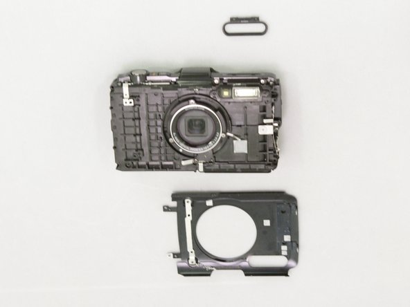
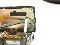
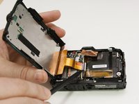
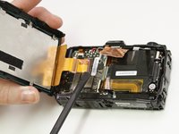
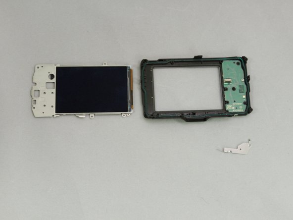
Next pry up on the white connector using the spudger to free the screen from the device.
-
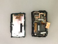
The housing and monitor will be separated.
-
-
-
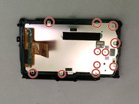
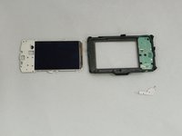
On the back of the separated monitor, remove the 10 silver Phillips #00 4.4mm screws and the 1 black Phillips #00 3.26mm screw.
-
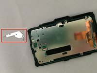
Use your fingers to remove the small corner metal triangle.
-
-
-
Using the spudger on the edge of the screen to lift it and remove the metal backing attached to the screen.
-


To reassemble your device, follow these instructions in reverse order.
To reassemble your device, follow these instructions in reverse order.
crwdns2935221:0crwdne2935221:0
crwdns2935227:0crwdne2935227:0
crwdns2915084:0crwdne2915084:0

Eastern Washington University, Team 1-2, Rowley SU 2015 crwdns2935289:0Eastern Washington University, Team 1-2, Rowley SU 2015crwdne2935289:0
EWU-ROWLEY-SU15S1G2
crwdns2931471:03crwdne2931471:0
crwdns2935297:04crwdne2935297:0