crwdns2942213:0crwdne2942213:0
-
crwdns2935201:0crwdne2935201:0 crwdns2935203:0crwdne2935203:0
-
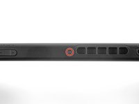
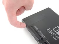
Press and hold down the small round button on the back of the Joy Con controller.
-
While you hold down the button, slide the controller upward.
-
-
crwdns2935201:0crwdne2935201:0 crwdns2935203:0crwdne2935203:0
-
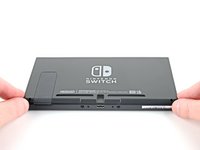
Continue sliding the Joy Con upward until it's completely removed from the console.
-
-
crwdns2935201:0crwdne2935201:0 crwdns2935203:0crwdne2935203:0
crwdns2935267:0crwdne2935267:0Magnetic Project Mat$17.96-
Use a Y00 screwdriver to remove the four 6.3 mm-long screws securing the rear panel.
-
-
crwdns2935201:0crwdne2935201:0 crwdns2935203:0crwdne2935203:0
-
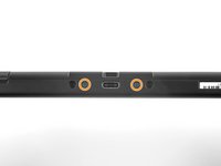
Use a JIS 00 driver to remove the following screws securing the rear panel:
-
One 2.5 mm-long screw on the top edge of the device
-
Two 2.5 mm-long screws on the bottom edge of the device
-
-
crwdns2935201:0crwdne2935201:0 crwdns2935203:0crwdne2935203:0
-
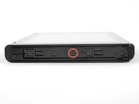
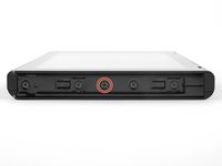
Use a JIS 00 driver to remove the two 3.8 mm center screws on the sides of the device (one on each side).
-
-
crwdns2935201:0crwdne2935201:0 crwdns2935203:0crwdne2935203:0
-
Use your finger to flip up the kickstand on the back of the device.
-
-
crwdns2935201:0crwdne2935201:0 crwdns2935203:0crwdne2935203:0
-
Use a JIS 00 driver to remove the 1.6 mm screw in the kickstand well.
-
Close the kickstand.
-
-
-
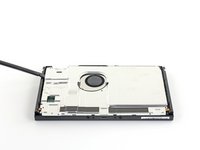
crwdns2935201:0crwdne2935201:0 crwdns2935203:0crwdne2935203:0
-
Open the game card cartridge flap.
-
Lift the rear panel up from the bottom of the device and remove it.
-
-
crwdns2935201:0crwdne2935201:0 crwdns2935203:0crwdne2935203:0
-
Use a JIS 00 driver to remove the 3.1 mm screw securing the microSD card reader to the device.
-
-
crwdns2935201:0crwdne2935201:0 crwdns2935203:0crwdne2935203:0
crwdns2935267:0crwdne2935267:0Tweezers$4.99-
Use your fingers or a pair of tweezers to lift the microSD card reader straight up from the device to disconnect and remove it.
-
-
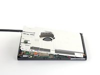
crwdns2935201:0crwdne2935201:0 crwdns2935203:0crwdne2935203:0
-
Use a JIS 00 driver to remove the six 3 mm screws securing the shield plate to the device.
-
-
crwdns2935201:0crwdne2935201:0 crwdns2935203:0crwdne2935203:0
crwdns2935267:0crwdne2935267:0Tweezers$4.99-
Use your fingers or a pair of tweezers to peel back the piece of foam on the top edge of the device near the fan exhaust port.
-
-
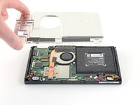
crwdns2935201:0crwdne2935201:0 crwdns2935203:0crwdne2935203:0
-
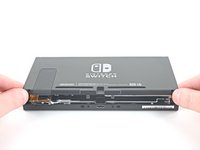
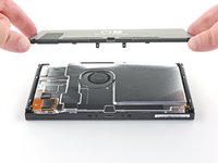
Insert a spudger underneath the shield plate along the edge of the device.
-
Pry up to lift the shield plate and remove it from the device.
-
You can reuse the pink thermal compound if you're careful. Keep the compound clean and make sure it makes solid contact between the heat sink and the shield during reassembly.
-
If you need to replace it, refer to our thermal paste guide to remove the old thermal compound and replace it with an appropriate compound, such as K5 Pro, during reassembly.
-
-
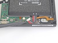
crwdns2935201:0crwdne2935201:0 crwdns2935203:0crwdne2935203:0
-
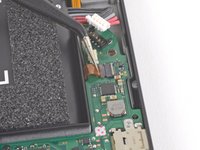
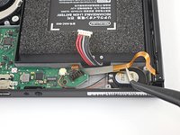
Use the point of a spudger to pry the battery connector straight up and out of its socket on the motherboard.
-
-
crwdns2935201:0crwdne2935201:0 crwdns2935203:0crwdne2935203:0
-
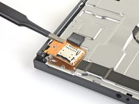
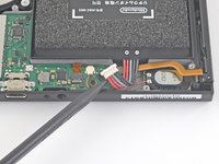
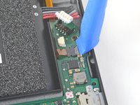
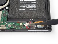
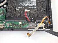
Use an opening tool, spudger, or your fingernail to flip up the small, hinged locking flap on the Joy Con rail data cable's ZIF connector.
-
-
crwdns2935201:0crwdne2935201:0 crwdns2935203:0crwdne2935203:0
crwdns2935267:0crwdne2935267:0Tweezers$4.99-
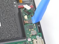
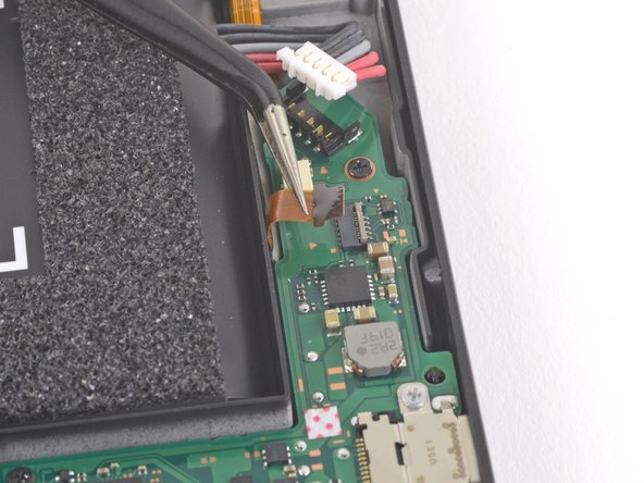
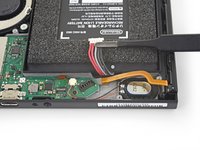
Use a pair of tweezers to slide the Joy Con rail data cable out of its connector on the motherboard.
-
-
crwdns2935201:0crwdne2935201:0 crwdns2935203:0crwdne2935203:0
-
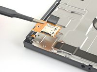
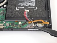
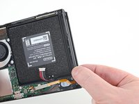
Use your fingers or a pair of tweezers to lift the battery connector up and out of the way of the Joy Con rail's data cable.
-
-
crwdns2935201:0crwdne2935201:0 crwdns2935203:0crwdne2935203:0
-
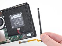
Use your fingers or a pair of tweezers to slide the Joy Con rail data cable out from under the motherboard.
-
-
crwdns2935201:0crwdne2935201:0 crwdns2935203:0crwdne2935203:0
-
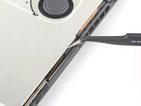
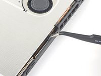
Use a JIS 00 driver to remove the four 3.7 mm screws securing the left Joy Con rail to the frame of the device.
-
-
crwdns2935201:0crwdne2935201:0 crwdns2935203:0crwdne2935203:0
-
Remove the left Joy Con sensor rail from the device.
-


crwdns2935221:0crwdne2935221:0
crwdns2935229:068crwdne2935229:0

crwdns2947412:08crwdne2947412:0
If this was a neon Switch, this would be the rail that gets attached with the blue or the red joy con?
it would be the Blue joy con
I completed this guide, but the left joy con is still not being detected after the sensor rail was replaced with a sensor rail purchased on this site. The joy con in question will attach and sync with another console, so that leads me to believe it is a fault with the switch console itself. Is there something else that I can replace that would fix this issue?
Depending on where you get your replacement rail, it may not have the silver on the ribbon cable. No worries, as I did this repair 3 months ago (Jan) and had no issues at all.
To get the ribbon cable in place, I recommend first getting the battery wires out of the way, then slightly bending it and sliding it under that section of the Motherboard. If you do it right, the end of the ribbon cable will pop up and that can be slid into place. Took some fiddling but I eventually got it to work!
No matter what, never crease your ribbon cables!
I have a joycon where it will disconnect if it is slotted all the way down. I have to push it up about 1mm for it to stay connected. The joycon works perfectly on other Switch consoles. Any idea of what troubleshooting I can try before replacing the whole rail?