crwdns2933423:0crwdne2933423:0

Nintendo GameCube Lens Recalibration

crwdns2942213:0crwdne2942213:0

  1. Nintendo GameCube Lens Recalibration, Disassembling the exterior case: crwdns2935265:01crwdnd2935265:01crwdnd2935265:02crwdne2935265:0 Nintendo GameCube Lens Recalibration, Disassembling the exterior case: crwdns2935265:01crwdnd2935265:02crwdnd2935265:02crwdne2935265:0
    • Flip the GameCube upside down.

    • Use a 4.5 mm gambit screwdriver to unscrew the four screws located on each corner (as shown in the second picture).

    • Remember to put all screws aside and out of the way from risk of being lost

    • With the four screws removed, flip the Gamecube back over to the original position.

    • Make sure to hold the bottom wall so it does not come off when flipping back over.

  2. Nintendo GameCube Lens Recalibration: crwdns2935265:02crwdnd2935265:01crwdnd2935265:02crwdne2935265:0 Nintendo GameCube Lens Recalibration: crwdns2935265:02crwdnd2935265:02crwdnd2935265:02crwdne2935265:0
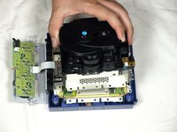
    • Using both hands, grasp the top of the Gamecube and carefully slide off the top wall exposing the inside of the unit.

    • Set aside the top wall.

  3. Nintendo GameCube Lens Recalibration, Removing the front and back panels: crwdns2935265:03crwdnd2935265:01crwdnd2935265:02crwdne2935265:0 Nintendo GameCube Lens Recalibration, Removing the front and back panels: crwdns2935265:03crwdnd2935265:02crwdnd2935265:02crwdne2935265:0
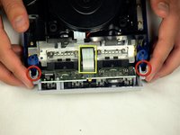
    • On opposite sides of the front panel you will see two (2) clips that attach the front panel to the front of the console. Remove the front panel by pressing on the two clips as shown in picture 1

    • The ribbon attaching the Gamecube to the front panel does not need to be removed, let the front panel rest at the front of the console.

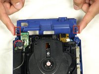
    • Remove the rear panel using the same technique used for the front panel, as shown in picture two.

  4. Nintendo GameCube Lens Recalibration, Removing the cooling fan: crwdns2935265:04crwdnd2935265:01crwdnd2935265:02crwdne2935265:0 Nintendo GameCube Lens Recalibration, Removing the cooling fan: crwdns2935265:04crwdnd2935265:02crwdnd2935265:02crwdne2935265:0
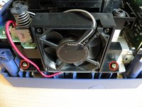
    • Unscrew the two screws using a #2 phillips screwdriver.

    • It is not necessary to detach the cooling fan wire from the power button switch board.

    • Slightly lift the cooling fan; slide it outwards and away from the rest of the Gamecube and lay it off to the side of the console.

  5. Nintendo GameCube Lens Recalibration, Removing the optical drive main screws: crwdns2935265:05crwdnd2935265:01crwdnd2935265:03crwdne2935265:0 Nintendo GameCube Lens Recalibration, Removing the optical drive main screws: crwdns2935265:05crwdnd2935265:02crwdnd2935265:03crwdne2935265:0 Nintendo GameCube Lens Recalibration, Removing the optical drive main screws: crwdns2935265:05crwdnd2935265:03crwdnd2935265:03crwdne2935265:0
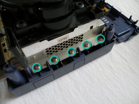
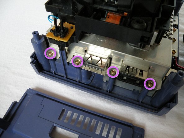
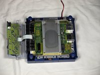
    • Locate and remove the twelve (12) Phillips #2 screws around the outside of the metal chassis located underneath the optical drive.

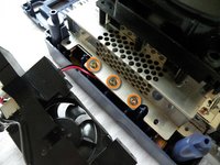
    • Three (3) of the twelve (12) screws are located underneath the cooling fan housing

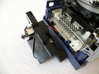
    • Five (5) of the twelve (12) screws are located to the right of the optical drive unit. Refer to picture 2.

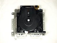
    • Four (4) of the twelve (12) screws are located to the rear of the unit, shown in picture 3.

  6. Nintendo GameCube Lens Recalibration, Memory card ground springs: crwdns2935265:06crwdnd2935265:01crwdnd2935265:01crwdne2935265:0
    • Remove the four phillips #1 screws securing the memory card ground springs located at the front of the console

    • Remove the ground springs and set them aside

  7. Nintendo GameCube Lens Recalibration, Removing the optical drive: crwdns2935265:07crwdnd2935265:01crwdnd2935265:03crwdne2935265:0 Nintendo GameCube Lens Recalibration, Removing the optical drive: crwdns2935265:07crwdnd2935265:02crwdnd2935265:03crwdne2935265:0 Nintendo GameCube Lens Recalibration, Removing the optical drive: crwdns2935265:07crwdnd2935265:03crwdnd2935265:03crwdne2935265:0
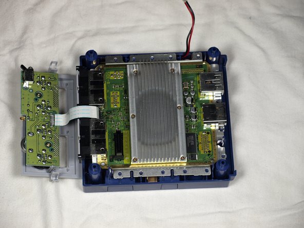
    • Carefully remove the optical drive unit.

    • The optical drive unit is connected to the main motherboard via a slot, located at the front right of the unit, so some force will be needed when removing the unit.

    • Carefully place the rest of the Gamecube unit aside and focus on the optical drive. Refer to picture 3.

  8. Nintendo GameCube Lens Recalibration, Optical drive metallic chassis: crwdns2935265:08crwdnd2935265:01crwdnd2935265:02crwdne2935265:0 Nintendo GameCube Lens Recalibration, Optical drive metallic chassis: crwdns2935265:08crwdnd2935265:02crwdnd2935265:02crwdne2935265:0
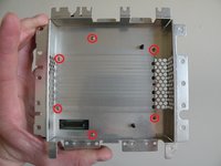
    • Underneath the now detached optical drive unit are six (6) Phillips #1 screws holding the metal chassis to the optical drive unit.

    • Remove all six screws and place the metal chassis to the side.

    • For this next step its recommended you place an old Gamecube disc on the optical drive unit to protect the lens from being scratched.

    • Take care not to damage the brown ribbon underneath as you do this. Picture 2 for reference.

  9. Nintendo GameCube Lens Recalibration, The potentiometer: crwdns2935265:09crwdnd2935265:01crwdnd2935265:01crwdne2935265:0
    • The potentiometer is located as shown in the picture. It's a very small cross-wing screw mounted on top of a little black box.

    • Now we need to adjust the potentiometer to make the optical lens laser stronger.

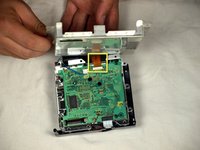
    • Using a very small flat head precision screwdriver turn the potentiometer no more than 3 degrees counter-clockwise.

    • Turning the potentiometer too much can result in the laser becoming too strong and actually burn the discs!

    • Turning the potentiometer clockwise would just result in a weaker laser and create even more DRE messages.

  10. Nintendo GameCube Lens Recalibration, Testing and further adjustments: crwdns2935265:010crwdnd2935265:01crwdnd2935265:01crwdne2935265:0
    • To test the lens calibration reassemble the console up to the ground springs near the memory card slots.

    • The memory card ground springs MUST be put back on prior to restarting your console.

    • If any further adjustments are necessary just turn the potentiometer no more than 1 or 2 degrees more per readjustment. Eventually you'll start to see less DRE messages.

    • Once there no more DRE messages, turn the potentiometer a further 1 degrees to "future-proof" your lens from DRE messages in the future.

    • As stated in the title of this guide. This procedure may not fix your DRE problems if the faut lies elsewhere in the system. But this will cover about 98% of DRE messages.

crwdns2915888:0crwdne2915888:0

To reassemble your device, follow these instructions in reverse order.

crwdns2935229:010crwdne2935229:0

Christopher Cox

crwdns2935283:004/20/12crwdne2935283:0

808 crwdns2915208:0crwdne2915208:0

crwdns2935295:0crwdne2935295:0

crwdns2944067:05crwdne2944067:0

Marvellous guide! It fixed the issue of erratic messages of "No Disc inserted..." or "Insert GameCube Disc...". Now my GC is as good as new! Thanks :D

jmromeroarguello - crwdns2934203:0crwdne2934203:0

Hey, I was reading two guides, this one and another one, which says I should use a philips head, while yours says a flat head, so what should I use?

Omar G - crwdns2934203:0crwdne2934203:0

Hi Omar, I would guess that either would work, but judging on the image in the other guide (which is much bigger), it looks like it might be a Phillips screw https://d3nevzfk7ii3be.cloudfront.net/ig...

Sam Goldheart -

Hi, is there a different measurement than 3 degrees? Don’t want to screw anything up, but I don’t really understand.

Claire - crwdns2934203:0crwdne2934203:0

The 3 degrees is not an official measurement for this. But just make EXTREMELY small adjustments. Think of it like turning the hands on a clock. 15 minutes would be 90 degrees or 1/4 turn. So you can imagine how small these adjustments are.

Christopher Cox -

crwdns2917038:0crwdne2917038:0

crwdns2936625:0crwdne2936625:0:

crwdns2936751:024crwdne2936751:0 10

crwdns2936753:07crwdne2936753:0 50

crwdns2936753:030crwdne2936753:0 234

crwdns2942667:0crwdne2942667:0 16,778