crwdns2933423:0crwdne2933423:0

Nintendo GameCube Front and Back Panel Replacement

crwdns2942213:0crwdne2942213:0

  1. Nintendo GameCube Front and Back Panel Replacement, Top Case: crwdns2935265:01crwdnd2935265:01crwdnd2935265:03crwdne2935265:0 Nintendo GameCube Front and Back Panel Replacement, Top Case: crwdns2935265:01crwdnd2935265:02crwdnd2935265:03crwdne2935265:0 Nintendo GameCube Front and Back Panel Replacement, Top Case: crwdns2935265:01crwdnd2935265:03crwdnd2935265:03crwdne2935265:0
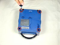
    • Turn over the Gamecube so that the bottom side is facing up.

    • Use the 4.5 mm Gamebit screwdriver to remove all four screws.

  2. Nintendo GameCube Front and Back Panel Replacement: crwdns2935265:02crwdnd2935265:01crwdnd2935265:03crwdne2935265:0 Nintendo GameCube Front and Back Panel Replacement: crwdns2935265:02crwdnd2935265:02crwdnd2935265:03crwdne2935265:0 Nintendo GameCube Front and Back Panel Replacement: crwdns2935265:02crwdnd2935265:03crwdnd2935265:03crwdne2935265:0
    • With the bottom side of the GameCube facing upward and the screws removed, carefully pull the outer shell of the unit away from the top half.

    • Move the GameCube so that the inside is facing upwards.

  3. Nintendo GameCube Front and Back Panel Replacement, Removing the back panel: crwdns2935265:03crwdnd2935265:01crwdnd2935265:01crwdne2935265:0
    • Gently press down on the clips located on either side of the back panel.

    • Carefully remove the back panel from the GameCube.

  4. Nintendo GameCube Front and Back Panel Replacement: crwdns2935265:04crwdnd2935265:01crwdnd2935265:01crwdne2935265:0
    • Unclip the controller ports at the front of the unit.

    • A ribbon cable (outlined in orange) is still attached to the unit. Do not disconnect this cable.

    • Controller ports are where the controllers plug into the game console, and are a half circular shape.

  5. Nintendo GameCube Front and Back Panel Replacement, Separate the casing: crwdns2935265:05crwdnd2935265:01crwdnd2935265:02crwdne2935265:0 Nintendo GameCube Front and Back Panel Replacement, Separate the casing: crwdns2935265:05crwdnd2935265:02crwdnd2935265:02crwdne2935265:0
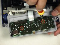
    • Use a Phillips #2 screwdriver to remove the two screws on the back of the control port.

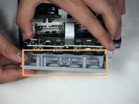
    • Carefully separate the gray outer casing of the control port and the circuit board.

crwdns2915888:0crwdne2915888:0

To reassemble your device, follow these instructions in reverse order.

crwdns2935229:04crwdne2935229:0

dcarlin

crwdns2935283:011/05/09crwdne2935283:0

301 crwdns2915208:0crwdne2915208:0

crwdns2935297:04crwdne2935297:0

crwdns2915084:0crwdne2915084:0

Cal Poly, Team 6-2, Maness Fall 2009 crwdns2935289:0Cal Poly, Team 6-2, Maness Fall 2009crwdne2935289:0

CPSU-MANESS-F09S6G2

crwdns2931471:04crwdne2931471:0

crwdns2935297:044crwdne2935297:0

crwdns2944067:00crwdne2944067:0

crwdns2917038:0crwdne2917038:0

crwdns2936625:0crwdne2936625:0:

crwdns2936751:024crwdne2936751:0 4

crwdns2936753:07crwdne2936753:0 23

crwdns2936753:030crwdne2936753:0 131

crwdns2942667:0crwdne2942667:0 14,238