crwdns2915892:0crwdne2915892:0
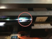
The 72-PIN connector is a piece of hardware inside of the game console. It has 72 metal pins, which come into contact with the metal spokes inside of the game cartridge to register the game. The pins on the connector bend out of place over time, and the game console can no longer register your games. This guide will show you how to locate and remove your worn out 72-PIN connector.
crwdns2942213:0crwdne2942213:0
-
-
Remove the six 13.25mm Phillips screws on the bottom of the game console with a #2.5 flathead screwdriver.
-
Flip the game console right side up and take off the top by pulling it up and away from the rest of the device with your hands.
-
-
-
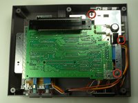
Remove the seven 13.25mm Phillips screws from the metal cover with a Phillips head #2 screwdriver.
-
Remove the metal cover by pulling it up and away from the rest of the console with your hands.
-
-
-
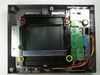
Remove the two silver 17.45mm Phillips screws from the cartridge tray using a Phillips head #2 screwdriver.
-
Remove the two bronze 13.25mm Phillips screws from the cartridge tray using a Phillips head #2 screwdriver.
-
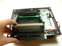
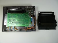
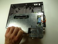
Slide the cartridge tray toward you, away from the 72-PIN connector, and off the motherboard assembly.
-
-
-
-
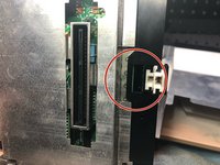
Note: Underneath the cartridge tray is a black trapezoid-shaped tab/lip (see marker). When properly assembled this tab/lip goes below the motherboard and shielding as seen here.
-
-
-
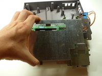
Remove the three 13.25mm Phillips screws that secure the motherboard to the lower case with a Phillips head #2 screwdriver.
-
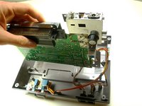
Pull the motherboard assembly straight up and out of the plastic case with your hands.
-
-
-
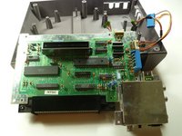
Disconnect the wire harnesses from the motherboard assembly:
-
Controller 1 (left)
-
Controller 2 (right)
-
Power
-
-
-
Lift off the EMI shield (metal cover) from the motherboard assembly.
-


To reassemble your device, follow these instructions in reverse order.
crwdns2935221:0crwdne2935221:0
crwdns2935229:088crwdne2935229:0
crwdns2935287:0crwdne2935287:0

Cal Poly, Team 14-40, Forte Fall 2010 crwdns2935289:0Cal Poly, Team 14-40, Forte Fall 2010crwdne2935289:0
CPSU-FORTE-F10S14G40
crwdns2931471:04crwdne2931471:0
crwdns2935297:028crwdne2935297:0
crwdns2947412:013crwdne2947412:0
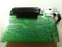
Because it wasn't terribly clear, the pin connector pulls off from the motherboard. Just pull straight away from the board to clear the connector. It takes some force to get it off.
And, no wires need to be disconnected either.
Very easy repair.
"How to replace your 72 pin connector"
Leaves out the steps that show how to remove the 72 pin connector.
Priceless
Um are we missing the last steps on how to actually remove the 72pin connector???
I replaced mine, and I'm still getting a solid white screen. Any ideas what else it might be?