crwdns2915892:0crwdne2915892:0
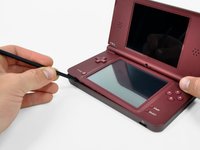
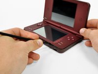
The lower display screen on the DSi XL is touch-sensitive. Regain touch control over your DSi with a new touchscreen.
crwdns2942213:0crwdne2942213:0
-
-
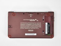
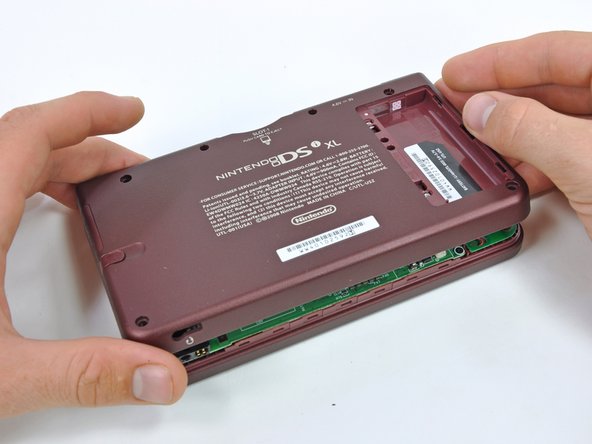
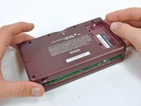
Remove the two Phillips screws securing the battery cover to the back of the handheld console.
-
Lift the battery cover off the back of the DSi XL.
-
-
-
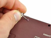
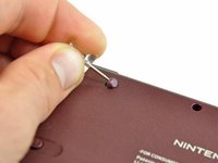
Remove the four rubber screw covers on the lower case by prying them up with a push pin.
-
-
-
Remove the following seven Phillips screws that secure the lower case to the rest of the DSi XL:
-
Four silver 5.3 mm screws
-
Two black 5.3 mm screws
-
One black 2.5 mm screw
-
-
-
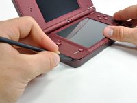
Insert a spudger between the upper and lower case at the bottom left corner of the DSi.
-
Slide the spudger along the bottom edge of the upper case to release the latches securing the upper case to the lower case.
-
-
-
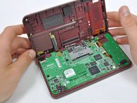
Lift the lower case from the front edge.
-
Rotate the lower case away from the DSi.
-
-
-
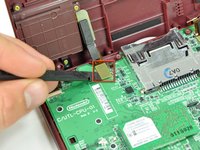
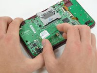
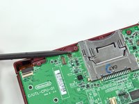
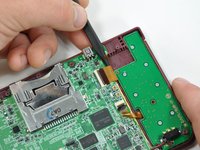
Using a spudger, pry the SD card/right shoulder button connector off its socket.
-
Pry the volume button/left shoulder button connector off its socket on the motherboard with a spudger.
-
-
-
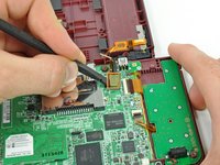
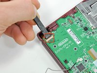
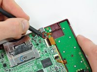
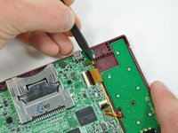
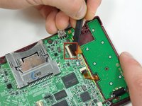
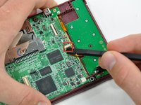
Lift the Wi-Fi board up off its socket on the motherboard.
-
-
-
Use a spudger to pry the Wi-Fi cable off its socket on the underside of the Wi-Fi board.
-
-
-
-
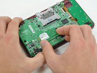
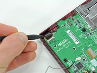
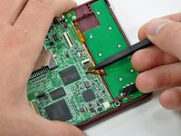
Use a spudger to pry the microphone cable off the motherboard.
-
-
-
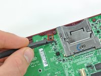
Using the flat end of a spudger, flip up the retaining flap on the camera ribbon ZIF connector.
-
Use the pointed end of a spudger to pull the camera ribbon from the ZIF connector.
-
-
-
Using the flat end of a spudger, flip up the retaining flap on the touchscreen cable ZIF connector.
-
With the pointed end of the spudger, pull the touchscreen cable from its connector on the motherboard.
-
-
-
Using the flat end of a spudger, flip up the retaining flap on the backlight cable ZIF connector.
-
With the pointed end of the spudger, pull the backlight cable from its connector on the motherboard.
-
-
-
Using the flat end of a spudger, flip up the retaining flap on the lower display data cable ZIF connector.
-
With the pointed end of the spudger, pull the lower display data cable from its connector on the motherboard.
-
-
-
Using the flat end of a spudger, flip up the retaining flap on the ZIF connector for the D-Pad/power button cable.
-
With the pointed end of the spudger, pull the D-Pad/power button cable from its connector on the motherboard.
-
-
-
Using the flat end of the spudger, pry the battery cable up off its socket on the motherboard.
-
-
-
Remove the screws securing the motherboard to the upper case:
-
A single 2.5 mm silver Phillips screw
-
Four 3.7 mm black Phillips screws
-
-
-
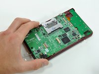
Deroute the microphone and antenna cables through the slot in the motherboard.
-
-
-
Rotate the motherboard off the lower case.
-
-
-
Using the flat end of a spudger, flip up the retaining flap on the upper display data cable ZIF connector.
-
With the pointed end of the spudger, pull the upper display data cable from its connector on the underside of the motherboard.
-
-
-
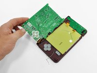
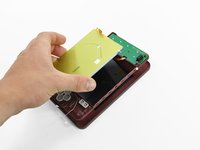
With the console still upside-down, open the DSi XL slightly.
-
Push the lower display away from the upper case.
-
Remove the lower display from the DSi XL.
-
-
-
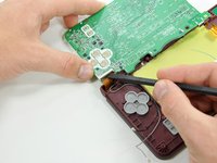
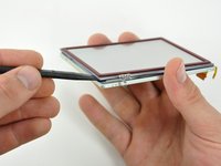
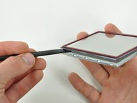
Insert a spudger between the touchscreen and top right corner of the display.
-
Slide the spudger down the right side of the display to free the edge of the touchscreen.
-
-
-
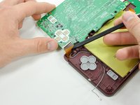
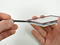
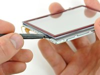
Continue around the bottom right corner of the display with the spudger.
-
Slide the spudger along the bottom edge of the touchscreen to separate it from the display.
-
-
-
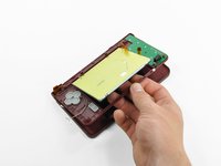
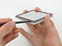
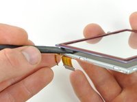
Continue around the bottom left corner of the display with a spudger.
-
Slide the spudger along the left edge of the touchscreen to remove it from the display.
-
-
-
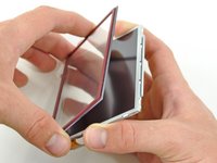
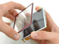
With three sides freed, remove the touchscreen from the lower display.
-


To reassemble your device, follow these instructions in reverse order.
To reassemble your device, follow these instructions in reverse order.
crwdns2935221:0crwdne2935221:0
crwdns2935229:019crwdne2935229:0

crwdns2947412:04crwdne2947412:0
Great tutorial, I completely missed the fact that the lower screen is TWO screens: the touchscreen and the proper screen. Nailed it!!
thankyou! <3
Step 16 = whole socket came off the motherboard with the least amount of effort. Tried soldering new contacts but too fine. Device now only good for parts.
Be super careful with p10 and p18 retention clips. If these come out, you are up the creek without a paddle.