crwdns2915892:0crwdne2915892:0
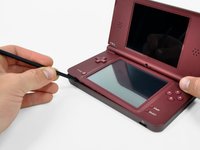
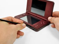
The lower display screen on the DSi XL is touch-sensitive. Regain touch control over your DSi with a new touchscreen.
crwdns2942213:0crwdne2942213:0
-
-
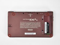
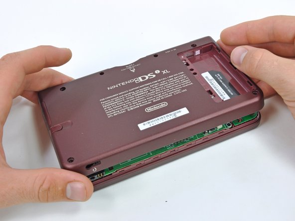
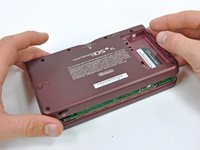
Remove the two Phillips screws securing the battery cover to the back of the handheld console.
-
Lift the battery cover off the back of the DSi XL.
 crwdns2952109:0crwdne2952109:0
-
-
-
Lift the battery from the DSi XL.
-
-
-
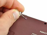
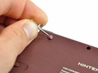
Remove the four rubber screw covers on the lower case by prying them up with a push pin.
-
-
-
Remove the following seven Phillips screws that secure the lower case to the rest of the DSi XL:
-
Four silver 5.3 mm screws
-
Two black 5.3 mm screws
-
One black 2.5 mm screw
-
-
-
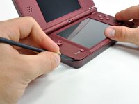
Insert a spudger between the upper and lower case at the bottom left corner of the DSi.
-
Slide the spudger along the bottom edge of the upper case to release the latches securing the upper case to the lower case.
-
-
-
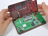
Lift the lower case from the front edge.
-
Rotate the lower case away from the DSi.
-
-
-
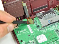
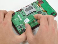
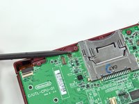
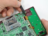
Using a spudger, pry the SD card/right shoulder button connector off its socket.
-
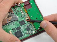
Pry the volume button/left shoulder button connector off its socket on the motherboard with a spudger.
-
-
-
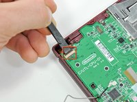
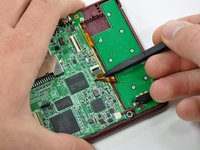
Lift the Wi-Fi board up off its socket on the motherboard.
-
-
-
Use a spudger to pry the Wi-Fi cable off its socket on the underside of the Wi-Fi board.
-
-
-
-
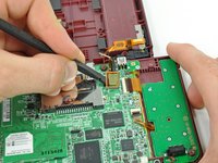
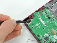
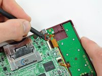
Use a spudger to pry the microphone cable off the motherboard.
-
-
-
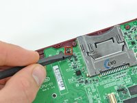
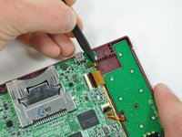
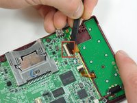
Using the flat end of a spudger, flip up the retaining flap on the camera ribbon ZIF connector.
-
Use the pointed end of a spudger to pull the camera ribbon from the ZIF connector.
-
-
-
Using the flat end of a spudger, flip up the retaining flap on the touchscreen cable ZIF connector.
-
With the pointed end of the spudger, pull the touchscreen cable from its connector on the motherboard.
-
-
-
Using the flat end of a spudger, flip up the retaining flap on the backlight cable ZIF connector.
-
With the pointed end of the spudger, pull the backlight cable from its connector on the motherboard.
-
-
-
Using the flat end of a spudger, flip up the retaining flap on the lower display data cable ZIF connector.
-
With the pointed end of the spudger, pull the lower display data cable from its connector on the motherboard.
-
-
-
Using the flat end of a spudger, flip up the retaining flap on the ZIF connector for the D-Pad/power button cable.
-
With the pointed end of the spudger, pull the D-Pad/power button cable from its connector on the motherboard.
-
-
-
Using the flat end of the spudger, pry the battery cable up off its socket on the motherboard.
-
-
-
Remove the screws securing the motherboard to the upper case:
-
A single 2.5 mm silver Phillips screw
-
Four 3.7 mm black Phillips screws
-
-
-
Deroute the microphone and antenna cables through the slot in the motherboard.
-
-
-
Rotate the motherboard off the lower case.
-
-
-
Using the flat end of a spudger, flip up the retaining flap on the upper display data cable ZIF connector.
-
With the pointed end of the spudger, pull the upper display data cable from its connector on the underside of the motherboard.
-
-
-
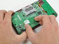
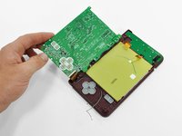
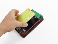
With the console still upside-down, open the DSi XL slightly.
-
Push the lower display away from the upper case.
-
Remove the lower display from the DSi XL.
-
-
-
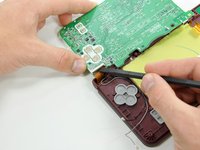
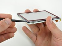
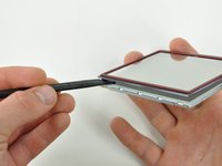
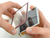
Insert a spudger between the touchscreen and top right corner of the display.
-
Slide the spudger down the right side of the display to free the edge of the touchscreen.
-
-
-
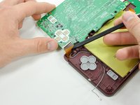
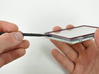
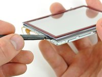
Continue around the bottom right corner of the display with the spudger.
-
Slide the spudger along the bottom edge of the touchscreen to separate it from the display.
-
-
-
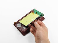
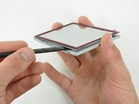
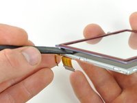
Continue around the bottom left corner of the display with a spudger.
-
Slide the spudger along the left edge of the touchscreen to remove it from the display.
-
-
-
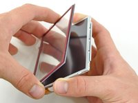
With three sides freed, remove the touchscreen from the lower display.
-


To reassemble your device, follow these instructions in reverse order.
crwdns2935221:0crwdne2935221:0
crwdns2935229:020crwdne2935229:0

crwdns2947412:04crwdne2947412:0
Great tutorial, I completely missed the fact that the lower screen is TWO screens: the touchscreen and the proper screen. Nailed it!!
luissebastianangeles - crwdns2934203:0crwdne2934203:0 crwdns2950251:0crwdne2950251:0
thankyou! <3
Zenn22 - crwdns2934203:0crwdne2934203:0 crwdns2950251:0crwdne2950251:0
Step 16 = whole socket came off the motherboard with the least amount of effort. Tried soldering new contacts but too fine. Device now only good for parts.
Reese Banister - crwdns2934203:0crwdne2934203:0 crwdns2950251:0crwdne2950251:0
Be super careful with p10 and p18 retention clips. If these come out, you are up the creek without a paddle.
Aaron Newman - crwdns2934203:0crwdne2934203:0 crwdns2950251:0crwdne2950251:0