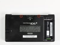
crwdns2915892:0crwdne2915892:0
Use this guide to replace your DSi's dual cameras and their shared ribbon cable.
crwdns2942213:0crwdne2942213:0
-
-
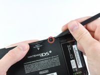
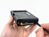
Unscrew the two Phillips screws securing the battery cover to the lower case.
-
Grasp the battery cover and lift it out of the lower case.
-
-
-
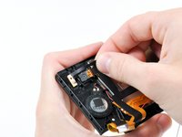
Using a spudger tool (or your fingernail), lift up the battery from the top.
-
Grasp the battery and remove it from the DSi.
-
-
-
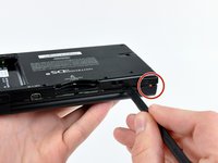
Two screws are hidden underneath two rubber feet highlighted in red.
-
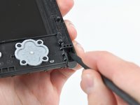
Use the tip of a spudger to pry the rubber feet out of the lower case.
-
-
-
Remove the following screws securing the lower case to the body of the DSi:
-
Six 5.2 mm Phillips #00 screws.
-
One 2.7 mm Phillips #00 screw.
-
-
-
Insert the spudger in between the lower casing and lower panel near the top right corner of the DSi.
-
Carefully run the spudger along the edge of the outer casing, creating an opening between the body and the casing.
-
Continue running the spudger around the body of the DSi until the majority of the lower case has been separated.
-
-
-
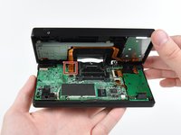
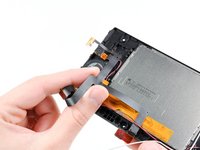
Carefully lift the lower casing from its bottom edge.
-
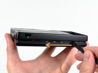
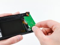
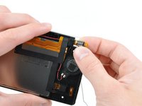
Pry the volume and SD board cable up from its socket on the motherboard using a spudger.
-
Once the cable is completely removed, then you may take off the entire outer casing.
-
-
-
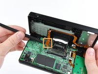
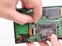
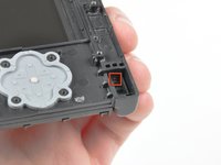
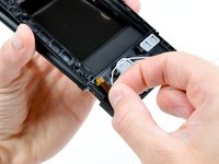
Pull the Wi-Fi board away from the motherboard by its edge closest to the headphone jack.
-
-
-
Pry the Wi-Fi antenna connector straight up from its socket on the Wi-Fi board.
-
-
-
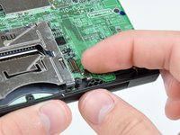
Use the tip of a spudger to pry the power board connector out of its socket on the motherboard.
-
-
-
crwdns2935267:0crwdne2935267:0Tweezers$4.99
-
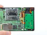
Use your fingernail or the edge of a plastic opening tool to flip up the retaining flap on the following three ZIF sockets:
-
Lower touchscreen cable
-
Lower LCD cable
-
Power board cable
-
After flipping up the locking tabs on all three sockets, use your fingers or a pair of tweezers to gently pull the cables straight out of their sockets.
-
-
-
Use your fingernail or the edge of a plastic opening tool to carefully flip up the touchscreen ribbon cable retaining flap.
-
Use the tip of a spudger to pull the touchscreen ribbon cable straight out of its socket.
-
-
-
Use your fingernail or the edge of a plastic opening tool to carefully flip up the dual camera ribbon cable retaining flap.
-
Use the tip of a spudger to pull the dual camera ribbon cable straight out of its socket.
-
-
-
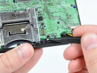
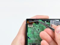
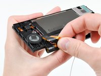
With the tip of a spudger, Pry the microphone antenna up off its socket on the motherboard.
-
-
-
Remove the following four Phillips screws securing the motherboard to the DSi framework.
-
Three longer screws.
-
One short screw.
-
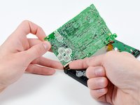
Pull the microphone and Wi-Fi antenna cables out of the notch cut into the motherboard near the headphone jack.
-
-
-
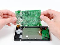
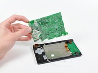
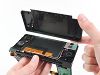
Slightly lift the motherboard upwards to reveal the upper LCD ribbon cable above the ABXY buttons .
-
Use your fingernail or the edge of a plastic opening tool to carefully flip up the upper LCD ribbon cable retaining flap.
-
Remove the motherboard from the DSi.
-
-
-
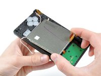
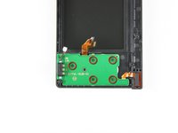
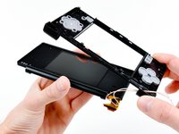
Use the tip of a spudger to pry the metal backing of the lower LCD up from the DSi's framework.
-
Lift the lower LCD assembly out of the DSi.
-
-
-
Use a pushpin to remove the four plastic screw covers (highlighted in red) on the front bezel.
-
-
-
Remove the four JIS screws securing the rear bezel to the front bezel.
-
-
-
Using two hands, gently slide the rear bezel upwards.
-
Lift the rear bezel straight up out of the DSi.
-
-
-
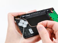
De-route the microphone and Wi-Fi antenna cables through the opening located on the bottom DSi's framework.
-
-
-
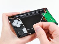
Remove the five JIS screws securing the power board to the DSi's framework.
-
Lift and remove the power board from the DSi.
-
-
-
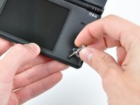
Push the metal hinge pin inward on the D-pad side of the front lower panel with the tip of a spudger.
-
The pin should move about 3 mm and stop. It is not necessary to try to completely remove the pin.
-
-
-
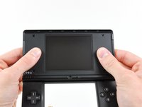
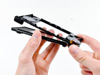
Slightly detach the lower and upper halves of the DSi.
-
De-route the upper LCD and dual camera ribbon cables through the slit near the ABXY side of the front lower panel.
-
Separate the lower and upper halves from each other.
-
-
-
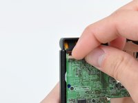
Using your fingers, grasp the microphone cable and remove it from the front bezel assembly.
-
The microphone will likely pop out of its housing, so it is probably easier to completely remove it at this point.
-
De-route the Wi-Fi antenna cable through the hinge.
-
-
-
Tightly coil the display and dual camera ribbon cables enough to push them through the steel hinge tube.
-
Remove the steel hinge tube.
-
Carefully push both coiled ribbon cables through the tube molded into the front upper panel.
-
-
-
Pry the front-facing camera straight up out of its housing in the front bezel.
-
-
-
Lift the rear-facing out of its housing in the front bezel.
-
Remove the dual camera cable assembly from the DSi.
-


To reassemble your device, follow these instructions in reverse order.
To reassemble your device, follow these instructions in reverse order.
crwdns2935221:0crwdne2935221:0
crwdns2935229:04crwdne2935229:0

crwdns2947412:03crwdne2947412:0
what happened if the pin goes in to far? (step 22)
I have a weird question: If I remove the cameras, and reassemble the device without them, will it still work?
It most likely will. My DSi is missing its camera assembly and works fine. Minus the features of the camera.
Elijah -