crwdns2915892:0crwdne2915892:0
Replace the speakers in your Nintendo DS Lite to bring sound back to your gaming experience!
crwdns2942213:0crwdne2942213:0
-
-
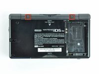
Unscrew the Phillips screw securing the battery cover to the lower case.
-
Pry the battery cover upward with a spudger or fingernail, and lift out of the lower case.
-
-
-
Wedge the edge of a spudger in between the side of the battery and the lower case housing and pry upward to dislodge the battery.
-
Remove the battery from the DS Lite.
-
-
-
Use the tip of a spudger to pry both rubber feet off the DS Lite.
-
-
-
Remove the following screws securing the lower case to the body of the DS Lite:
-
Two 4.3 mm gold Phillips screws
-
One 3.9 mm black Tri-point screw
-
One 3.3 mm silver Phillips screw
-
Three 5.5 mm silver Tri-point screws
-
-
-
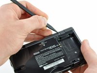
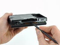
Insert the edge of a spudger in between the lower and upper case near the top right corner of the DS Lite.
-
Carefully run the spudger along the right edge of the DS Lite, creating an opening in the process.
-
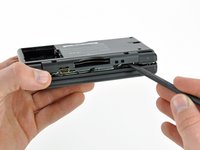
Continue running the spudger along the backside of the DS Lite until the majority of the lower case has been separated from the upper case.
-
-
-
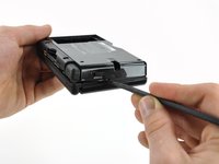
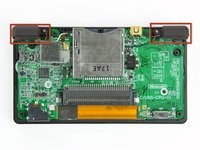
Lift the lower case away from the rest of the DS Lite.
-
-
-
Lift both trigger buttons out of the DS Lite.
-
-
-
Use the flat edge of a spudger to pry the Wi-Fi antenna connector straight up from its socket on the Wi-Fi board.
-
-
-
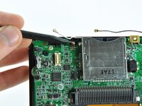
Use the flat edge of a spudger to pry the Wi-Fi board connector straight up from its socket on the motherboard.
-
-
-
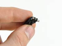
Use the flat edge of a spudger to separate the right edge of the Wi-Fi board from the motherboard.
-
Remove the Wi-Fi board from the DS Lite.
-
-
-
-
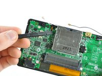
Use the flat edge of a spudger to pry the microphone connector straight up from its socket on the motherboard.
-
-
-
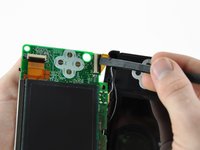
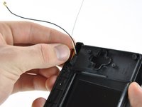
Position the antenna cable with its connector facing up and away from the motherboard using a spudger to hold it down lightly in the gap between chips on the motherboard.
-
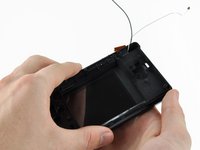
Slowly and carefully pull the antenna cable until the cable connector is under the DS Lite game cartridge reader.
-
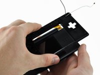
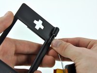
Continue pulling the cable until the cable connector comes out from under the game cartridge reader on the right side.
-
-
-
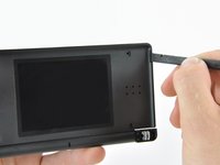
Use your fingernail or the edge of a spudger to carefully flip up the touchscreen ribbon cable retaining flap.
-
Use the tip of a spudger to pull the touchscreen ribbon cable straight out of its socket.
-
-
-
Remove the two 3.4 mm Phillips screws securing the motherboard to the upper case.
-
-
-
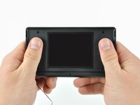
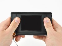
Open the display enough to use your finger to push the front edge of the motherboard up and away from the upper case.
-
-
-
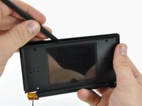
Use your fingernail or the flat edge of a spudger to carefully flip up the upper LCD ribbon cable retaining flap.
-
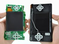
Pull the motherboard away from the DS Lite to separate the upper LCD ribbon cable from its socket on the motherboard.
-
Remove the motherboard from the DS Lite.
-
Now you may open the retaining flap for the lower LCD screen in the same way and separate the lower LCD screen from the motherboard.
-
-
-
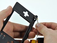
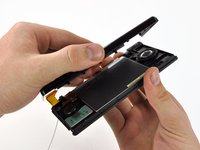
Remove the two 8.3 mm Phillips screws securing the upper case to the display assembly.
-
-
-
Pull the upper LCD ribbon cable to the right, through the slit in the case.
-
Push the ribbon cable down through the slit.
-
-
-
Slowly lift the upper case away from the display, making sure the ribbon cable does not get caught.
-
-
-
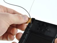
Once the ribbon cable is free from the upper case, pull the antenna and Wi-Fi cables through the hole in the upper case.
-
Remove the upper case from the DS Lite.
-
-
-
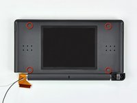
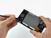
Use a push pin to remove the four plastic screw covers on the front bezel.
-
-
-
Remove the four 3.4 mm Phillips screws securing the rear display bezel to the front display bezel
-
-
-
Use the edge of a spudger to pry both rubber pads out of the front display bezel.
-
-
-
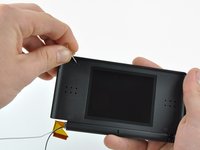
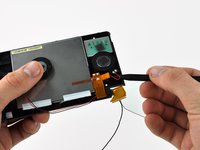
Using two hands, gently slide the rear bezel upwards.
-
-
-
Insert a spudger in the gap between the front and rear display bezels and pry the front bezel away from the rear bezel.
-
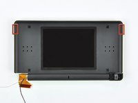
Lift the rear display bezel away from the display assembly.
-
-
-
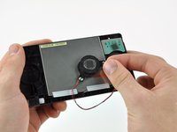
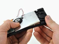
Use the tip of a spudger to pry both speakers up from their housing and place them on the back of the LCD.
-
-
-
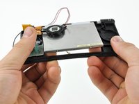
Starting in the top right corner, use both hands to slowly separate the LCD from the front display bezel.
-
Continue separating along the top and left edges of the LCD.
-
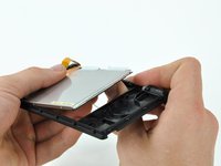
Finally, push the LCD up and away from the front display bezel.
-
-
-
Desolder the speakers from the upper LCD by heating up the solder joints with a soldering iron and simultaneously pulling the speaker wires away from the ribbon cable.
-
Speakers remain.
-


To reassemble your device, follow these instructions in reverse order.
To reassemble your device, follow these instructions in reverse order.
crwdns2935221:0crwdne2935221:0
crwdns2935229:016crwdne2935229:0

crwdns2947412:03crwdne2947412:0
what is the temperature for soldering the speakers off and inserting it back in?
Wouldn’t be easier to just get to the speakers, desolder the wires at the speaker and resolder new ones in?
Wouldn’t it be easier just to get to the speakers, unsolder the wires at the speakers, and resoldered new ones in?