crwdns2942213:0crwdne2942213:0
-
-
Remove the five screws on the bottom of the camera with a JIS #000 head screwdriver.
-
-
-
Remove the 3 screws under the battery flap and remove the bottom cover.
-
-
-
Remove the 2 screws inside the camera on the back corners.
-
-
-
Open the HDMI flap and remove the 2 screws.
-
-
-
Remove the screw next to the camera strap loop.
-
-
-
Remove the 2 screws on each side of the view finder.
-
-
-
-
Remove the 2 screws above and below the SD card flap.
-
-
-
Peel off the adhesive leather screw cover and remove the 2 screws under it.
-
-
-
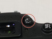
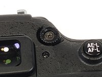
Remove the Diopter adjustment control sticker and remove the screw under it.
-
-
-
Separate the back panel of the camera from the actual camera.
-
-
-
Disconnect the LCD ribbon cables and power cable from the motherboard.
-
-
-
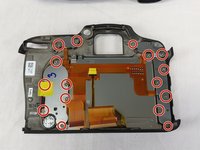
Unscrew all 16 screws around the back plate of the camera.
-
-
-
Then unscrew the remaining screws holding the back plate to the LCD.
-
Then simply remove the plate with the LCD.
-
-
-
Undo the 5 ribbon cable connectors by flipping the latches up with a plastic spudger.
-
-
-
Remove the black 4 pin connector by pulling it out of the connector.
-
-
-
Remove the 7 screws holding the motherboard in place.
-
-
-
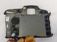
This is what you should see after removing the motherboard.
-
-
-
After following the guide to remove the back LCD screen from the motherboard, remove the 2 marked screws.
-


To reassemble your device, follow these instructions in reverse order.
To reassemble your device, follow these instructions in reverse order.
crwdns2935221:0crwdne2935221:0
crwdns2935227:0crwdne2935227:0
crwdns2915084:0crwdne2915084:0

USF Tampa, Team S11-G6, Cheng Spring 2018 crwdns2935289:0USF Tampa, Team S11-G6, Cheng Spring 2018crwdne2935289:0
USFT-CHENG-S18S11G6
crwdns2931471:04crwdne2931471:0
crwdns2935297:06crwdne2935297:0