crwdns2915892:0crwdne2915892:0
Use this guide to replace the motherboard.
Note: You'll need JIS screwdrivers for this repair. Regular Phillips screwdrivers have a cross pattern with rounded inner edges and won't fully fit the slots in the JIS screws. JIS screwdrivers instead have a straight cross pattern which makes much better contact with the screw head and is made for the high torque you will need to loosen the screws.
crwdns2942213:0crwdne2942213:0
-
-
Remove the following 5 screws securing the bottom cover to the camera body:
-
Four 6 mm J000 screws.
-
One 8 mm J000 screw (under lens mount).
-
-
-
Remove three 6 mm J000 screws from under the battery cover.
-
-
-
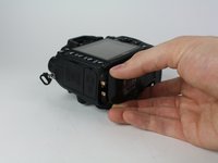
Gently pull the bottom cover off of the camera body.
-
-
-
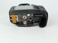
Remove the following screws from the port area:
-
Two 3.5 mm J000 screws.
-
One 6 mm J000 screw (right above ports).
-
-
crwdns2935267:0crwdne2935267:0Tweezers$4.99
-
Peel the rear rubber piece off with tweezers.
-
-
-
Remove one 4.25 mm J000 screw from behind the rear rubber piece.
-
-
-
Pull the eyepiece cover up to remove it.
-
-
-
Remove two 6 mm J000 screws from behind the eyepiece cover.
-
-
-
-
Open the SD card cover by pushing slightly down with your thumb and sliding up.
-
-
-
Remove four 6 mm J000 screws that secure the SD card cover.
-
-
-
Remove the following screws that secure the back case:
-
One 6 mm J000 screw.
-
One 3 mm J000 screw.
-
-
-
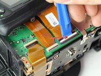
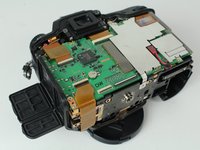
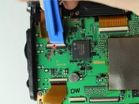
Disconnect the following two ribbon cables from the motherboard.
-
-
-
Remove the following screws securing the left motherboard shield:
-
One 2 mm J000 screw (on the bottom).
-
One 3.5 mm J000 screw (on the back).
-
-
-
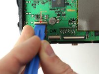
Gently pry and lift the left motherboard shield off.
-
-
-
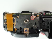
Remove one 3.5 mm J000 screw securing the right motherboard shield.
-
-
-
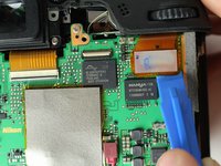
Gently lift the right motherboard shield off with the tip of a spudger.
-
-
-
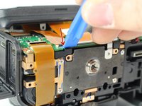
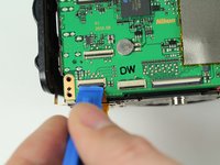
Carefully disconnect the red connector with tweezers.
-
-
-
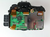
Remove four 3.5 mm J000 screws securing the motherboard.
-
-
-
Gently pull the port side cover away from the motherboard.
-


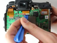


To reassemble your device, follow these instructions in reverse order.
To reassemble your device, follow these instructions in reverse order.
crwdns2935221:0crwdne2935221:0
crwdns2935229:09crwdne2935229:0
crwdns2915084:0crwdne2915084:0

Cal Poly, Team 24-6, Lancaster Spring 2015 crwdns2935289:0Cal Poly, Team 24-6, Lancaster Spring 2015crwdne2935289:0
CPSU-LANCASTER-S15S24G6
crwdns2931471:03crwdne2931471:0
crwdns2935297:06crwdne2935297:0
crwdns2947412:05crwdne2947412:0
Hi thank you.
perfekt. Thank you! Had to replace the board because the GPS port was brocken.
Hi, thanks for the detailed instructions! I just replaced my main board and the new one did not boot. The battery is charged, but the LCD shows nothing when battery is in and when the power is on. Is that a problem with the replacement main board or does it need to be programmed? I expected it to power up once the power is available.
Have you resolved your issue?
I get CLOCK with low battery indication . I checked internal battery health and I replaced with new battery on motherboard . Now with new battery in place I see voltage 3.12v and still camera does show CLOCK symbols with low battery. Please let me know if there is hard reset makes default configuration.