crwdns2915892:0crwdne2915892:0
Use this guide to replace the image sensor.
Note: You'll need JIS screwdrivers for this repair. Regular Phillips screwdrivers have a cross pattern with rounded inner edges and won't fully fit the slots in the JIS screws. JIS screwdrivers instead have a straight cross pattern which makes much better contact with the screw head and is made for the high torque you will need to loosen the screws.
crwdns2942213:0crwdne2942213:0
-
-
Remove the following 5 screws securing the bottom cover to the camera body:
-
Four 6 mm J000 screws.
-
One 8 mm J000 screw (under lens mount).
-
-
-
Remove three 6 mm J000 screws from under the battery cover.
Note for D7100: the screw marked red closest to the yellow battery guarding clip is 5.3mm long, the 2 other screws marked red are 6.0mm long.
-
-
-
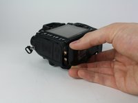
Gently pull the bottom cover off of the camera body.
Note for D7100: place your thumb in the battery compartment and your index outside the battery box. Gently pinch the bottom cover between thumb and index finger, and gently lift it from the camera body. It separates very easily.
-
-
-
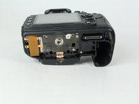
Remove the following screws from the port area:
-
Two 3.5 mm J000 screws.
-
One 6 mm J000 screw (right above ports).
Note for D7100: the 2 screws marked red under the rubber covers are hidden below the middle cover. These screws are 3.8mm long. The orange screw is 6.35mm long.
-
-
crwdns2935267:0crwdne2935267:0Tweezers$4.99
-
Peel the rear rubber piece off with tweezers.
This is not needed : if you don't touch this rubber & screw the SD card cover will come off at the same time that the back case.
= Quicker and easier
-
-
-
Remove one 4.25 mm J000 screw from behind the rear rubber piece.
This is not needed : if you don't touch this rubber & screw the SD card cover will come off at the same time that the back case.
= Quicker and easier
⚠️ Note for D7100: this step IS needed when disassembling the D7100 body as the rubber conceals 2 JIS #000 screws (5.5 mm at top and 3 mm at bottom). Without removing those 2 screws the back case won't separate from the body. When detaching the rubber cover, make sure to keep the small plastic cover embedded at the bottom of the rubber.
The SD card cover will fall out from the camera body when separating the back case.
-
-
-
Pull the eyepiece cover up to remove it.
-
-
-
Remove two 6 mm J000 screws from behind the eyepiece cover.
Concerning the diopter, it's wrong : D7000 also have a screw in it.
See step 41.
Note for D7100: the 2 screws to the side of the eyepiece are 5.3mm long.
Note for D7100: the screw holding the diopter dial is 11.4mm long.
-
-
-
Open the SD card cover by pushing slightly down with your thumb and sliding up.
-
-
-
-
Remove four 6 mm J000 screws that secure the SD card cover.
Note for D7100: these 4 screws are 6.30-6.35mm long
Los 4 tornillos miden 5mm en la D7000
-
-
-
Gently pull the SD card cover off.
Attention! High voltage. After removing the memory card cover, remove the yellow sticker and use a 220 volt 15 watt incandescent lamp to discharge the capacitor.
-
-
-
Remove the following screws that secure the back case:
-
One 6 mm J000 screw.
-
One 3 mm J000 screw.
On D7100 both screws are the same length at 6mm
En la D7000 ambos miden 4mm
-
-
-
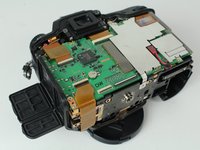
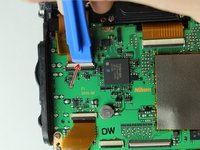
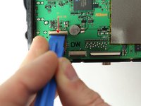
Disconnect the following two ribbon cables from the motherboard.
Note for D7100: the 2 ribbon cables that connect the back cover to the motherboard have ZIF sockets with the black lever at the bottom. Leave the other 2 (leftmost) ribbon cables at the bottom of the motherboard untouched.
-
-
-
Remove the following screws securing the left motherboard shield:
-
One 2 mm J000 screw (on the bottom).
-
One 3.5 mm J000 screw (on the back).
-
-
-
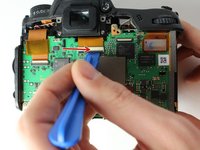
Gently pry and lift the left motherboard shield off.
No need to remove shield. Risk of damaging clips holding shield.
No Motherboard shield on D7100
-
-
-
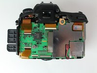
Remove one 3.5 mm J000 screw securing the right motherboard shield.
No need to remove shield. Risk of damaging clips holding shield.
-
-
-
Gently lift the right motherboard shield off with the tip of a spudger.
-
-
-
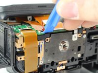
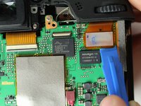
Disconnect remaining ribbon cables.
Note for D7100: at the top of the motherboard, there are 2 wide ZIF sockets (far left: white lever at top; far right: brown lever at bottom) and a narrow "no-fuss ribbon cable connector" (cable connector makes a 90° turn from 12 o' clock to 3 o'clock).
-
-
-
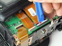
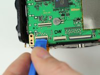
Disconnect remaining ribbon cables.
One more ribbon behind press down tab
Note for D7100: at the bottom of the motherboard, there are 3 ZIF sockets (far left, top: black lever at bottom; far left, bottom (underneath the previous): black lever at top; adjacent to the right: black lever at top).
-
-
-
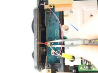
Carefully disconnect the red connector with tweezers.
-
-
-
Remove four 3.5 mm J000 screws securing the motherboard.
-
-
-
Gently pull the port side cover away from the motherboard.
-
-
-
Disconnect black and white speaker cable.
-
-
-
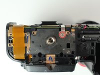
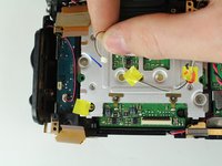
Remove three 6 mm J000 screws securing the image sensor.
Best to set markings on the three screws before removing sensor. To preserve alignment of sensor and body frame
This step is NOT necessary if you don't plan on doing anything with the sensor itself
-> just let it all attached together and save yourself time and energy
These 3 JIS #0 screws require quite some torque to unscrew.
Don't forget to open the ZIF connector of the sensor ribbon cable before removing the sensor board.
-
-
-
Carefully lift the image sensor plate out of the camera.
-


To reassemble your device, follow these instructions in reverse order.
To reassemble your device, follow these instructions in reverse order.
crwdns2935221:0crwdne2935221:0
crwdns2935229:019crwdne2935229:0
crwdns2915084:0crwdne2915084:0

Cal Poly, Team 24-6, Lancaster Spring 2015 crwdns2935289:0Cal Poly, Team 24-6, Lancaster Spring 2015crwdne2935289:0
CPSU-LANCASTER-S15S24G6
crwdns2931471:03crwdne2931471:0
crwdns2935297:05crwdne2935297:0
crwdns2947412:04crwdne2947412:0
I really need to do this operation! One question: I’m shopping for a replacement sensor and in the photos it looks like the cables off the sensor assembly are free hanging. In this tutorial there is only the disconnection of the black and white speaker cables. Where do these cables go?
I am grateful for this! Thanks - it worked a treat!
Thanks, I have done it with the Nikon d7200, it is different I have made some comments already, similar to the Nikon d7100 you have to unscrew the diopter and has 2 screws under the rubber what you have to remove… The motherboard is totally different
Any suggestions for locating a reputable, OEM part? Tons of choices on eBay with widely varying prices. Hints or clues to ensure I am buying authentic and safe parts are appreciated! Thanks!
Note for D7100: the rightmost screw marked red is 5.4mm long (to the right of the identification sticker with serial number), the 3 other screws marked red are 6.0mm long. The orange screw is 8.75mm long.
Olivier Biot - crwdns2934203:0crwdne2934203:0